2–12 Chapter 2: Cyclone IV Reset Control and Power Down
Transceiver Reset Sequences
Cyclone IV Device Handbook, September 2014 Altera Corporation
Volume 2
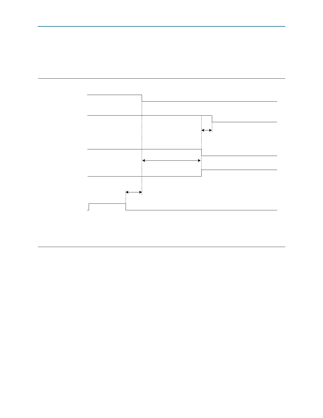
Receiver Only Channel—Receiver CDR in Manual Lock Mode
This configuration contains only a receiver channel. If you create a Receiver Only
instance in the ALTGX MegaWizard Plug-In Manager with receiver CDR in manual
lock mode, use the reset sequence shown in Figure 2–7.
As shown in Figure 2–7, perform the following reset procedure for the receiver CDR
in manual lock mode:
1. After power up, wait for the
busy
signal to be asserted.
2. Keep the
rx_digitalreset
and
rx_locktorefclk
signals asserted and the
rx_locktodata
signal deasserted during this time period.
3. After deassertion of the
busy
signal (marker 1), wait for two parallel clock cycles to
deassert the
rx_analogreset
signal (marker 2). After
rx_analogreset
deassert,
rx_pll_locked
will assert.
4. Wait for at least t
LTR_LTD_Manual
, then deassert the
rx_locktorefclk
signal. At the
same time, assert the
rx_locktodata
signal (marker 3).
5. Deassert
rx_digitalreset at least t
LTD_Manual
(the time between markers 3
and 4) after asserting the rx_locktodata signal. At this point, the
receiver is ready to receive data.
Figure 2–7. Sample Reset Sequence of Receiver Only Channel—Receiver CDR in Manual Lock Mode
Notes to Figure 2–7:
(1) For t
LTR_LTD_Manual
duration, refer to the Cyclone IV Device Datasheet chapter.
(2) For t
LTD_Manual
duration, refer to the Cyclone IV Device Datasheet chapter.
(3) The
busy
signal is asserted and deasserted only during initial power up when offset cancellation occurs. In subsequent reset sequences, the
busy
signal is asserted and deasserted only if there is a read or write operation to the ALTGX_RECONFIG megafunction.
Reset Signals
Output Status Signals
2
3
4
CDR Control Signals
3
1
Two parallel clock cycles
rx_analogreset
rx_digitalreset
rx_locktorefclk
rx_locktodata
busy (3)
t
LTR_LTD_Manual
(1)
t
LTD_Manual
(2)