Chapter 5: Clock Networks and PLLs in Cyclone IV Devices 5–31
Hardware Features
October 2012 Altera Corporation Cyclone IV Device Handbook,
Volume 1
■ When using manual clock switchover, the difference between
inclk0
and
inclk1
can be more than 20%. However, differences between the two clock sources
(frequency, phase, or both) can cause the PLL to lose lock. Resetting the PLL
ensures that the correct phase relationships are maintained between the input and
output clocks.
■ Both
inclk0
and
inclk1
must be running when the
clkswitch
signal goes high to
start the manual clock switchover event. Failing to meet this requirement causes
the clock switchover to malfunction.
■ Applications that require a clock switchover feature and a small frequency drift
must use a low-bandwidth PLL. When referencing input clock changes, the
low-bandwidth PLL reacts slower than a high-bandwidth PLL. When the
switchover happens, the low-bandwidth PLL propagates the stopping of the clock
to the output slower than the high-bandwidth PLL. The low-bandwidth PLL
filters out jitter on the reference clock. However, the low-bandwidth PLL also
increases lock time.
■ After a switchover occurs, there may be a finite resynchronization period for the
PLL to lock onto a new clock. The exact amount of time it takes for the PLL to
re-lock is dependent on the PLL configuration.
■ If the phase relationship between the input clock to the PLL and output clock from
the PLL is important in your design, assert
areset
for 10 ns after performing a
clock switchover. Wait for the locked signal (or gated lock) to go high before
re-enabling the output clocks from the PLL.
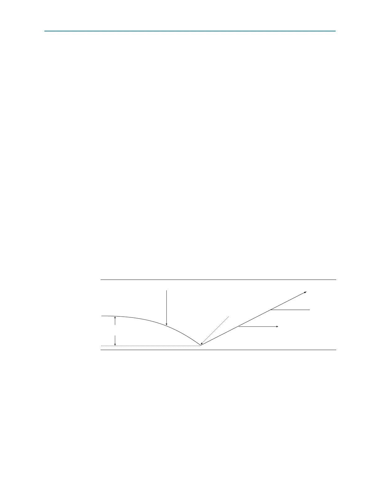
■ Figure 5–20 shows how the VCO frequency gradually decreases when the primary
clock is lost and then increases as the VCO locks on to the secondary clock. After
the VCO locks on to the secondary clock, some overshoot can occur (an
over-frequency condition) in the VCO frequency.
■ Disable the system during switchover if the system is not tolerant to frequency
variations during the PLL resynchronization period. You can use the
clkbad0
and
clkbad1
status signals to turn off the PFD (
pfdena
=
0
) so the VCO maintains its
last frequency. You can also use the switchover state machine to switch over to the
secondary clock. Upon enabling the PFD, output clock enable signals (
clkena
) can
disable clock outputs during the switchover and resynchronization period. After
the lock indication is stable, the system can re-enable the output clock or clocks.
Figure 5–20. VCO Switchover Operating Frequency
F
vco
Primary Clock Stops Running
Switchover Occurs
VCO Tracks Secondary Cloc
Frequency Overshoot