Chapter 8: Configuration and Remote System Upgrades in Cyclone IV Devices 8–51
Configuration
May 2013 Altera Corporation Cyclone IV Device Handbook,
Volume 1
1 If a non-Cyclone IV device is cascaded in the JTAG-chain,
TDO
of the non-Cyclone IV
device driving into
TDI
of the Cyclone IV device must fit the maximum overshoot
outlined in Equation 8–1 on page 8–5.
The
CONF_DONE
and
nSTATUS
signals are shared in multi-device AS, AP, PS, and FPP
configuration chains to ensure that the devices enter user mode at the same time after
configuration is complete. When the
CONF_DONE
and
nSTATUS
signals are shared among
all the devices, you must configure every device when JTAG configuration is
performed.
If you only use JTAG configuration, Altera recommends that you connect the circuitry
as shown in Figure 8–25 or Figure 8–26, in which each of the
CONF_DONE
and
nSTATUS
signals are isolated so that each device can enter user mode individually.
After the first device completes configuration in a multi-device configuration chain,
its
nCEO
pin drives low to activate the
nCE
pin of the second device, which prompts the
second device to begin configuration. Therefore, if these devices are also in a JTAG
chain, ensure that the
nCE
pins are connected to GND during JTAG configuration or
that the devices are JTAG configured in the same order as the configuration chain. As
long as the devices are JTAG configured in the same order as the multi-device
configuration chain, the
nCEO
of the previous device drives the
nCE
pin of the next
device low when it has successfully been JTAG configured. You can place other Altera
devices that have JTAG support in the same JTAG chain for device programming and
configuration.
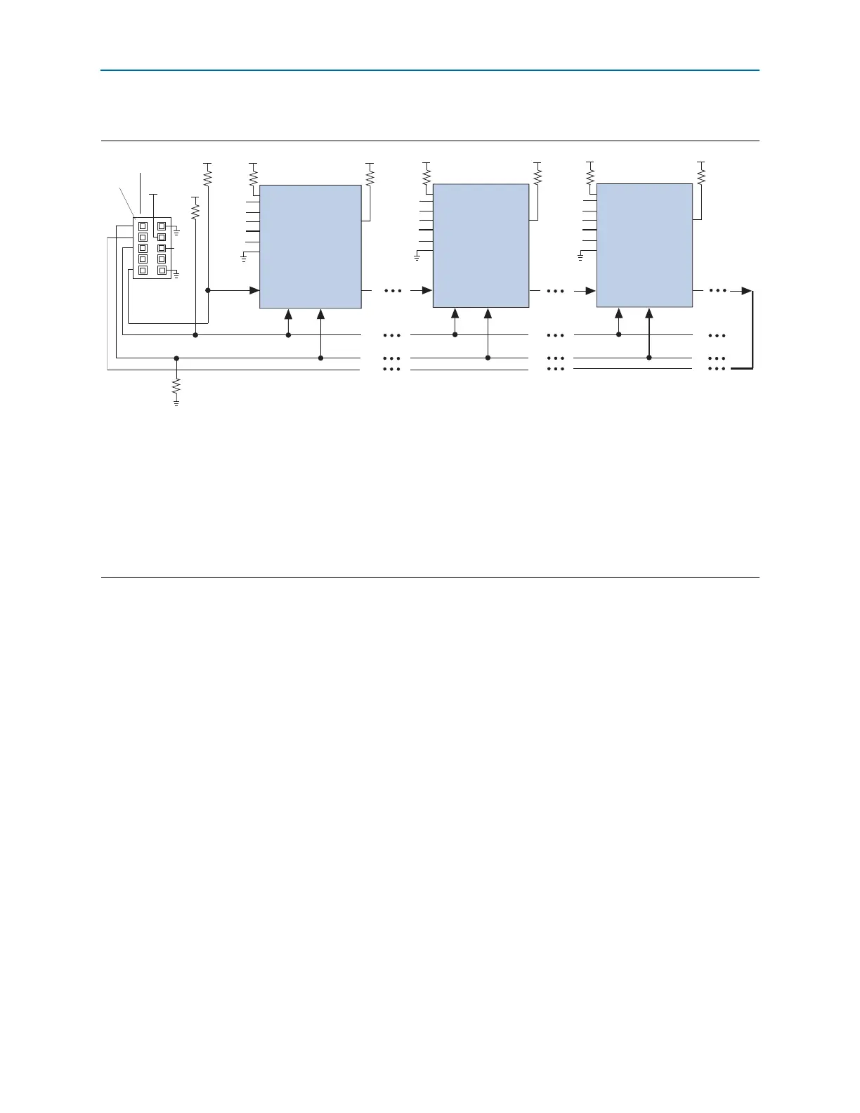
Figure 8–26. JTAG Configuration of Multiple Devices Using a Download Cable (1.2, 1.5, and 1.8-V V
CCIO
Powering the
JTAG Pins)
Notes to Figure 8–26:
(1) Connect these pull-up resistors to the V
CCIO
supply of the bank in which the pin resides.
(2) Connect the
nCONFIG
and
MSEL
pins to support a non-JTAG configuration scheme. If you only use a JTAG configuration, connect the
nCONFIG
pin to logic-high and the
MSEL
pins to GND. In addition, pull
DCLK
and
DATA[0]
to either high or low, whichever is convenient on your board.
(3) In the USB-Blaster and ByteBlaster II cable, this pin is connected to
nCE
when it is used for AS programming, otherwise it is a no connect.
(4) You must connect the
nCE
pin to GND or driven low for successful JTAG configuration.
(5) Power up the V
CC
of the ByteBlaster II or USB-Blaster cable with supply from V
CCIO
. The ByteBlaster II and USB-Blaster cables do not support a
target supply voltage of 1.2 V. For the target supply voltage value, refer to the ByteBlaster II Download Cable User Guide and the USB-Blaster
Download Cable User Guide.
(6) Resistor value can vary from 1 k to 10 k.
TMS TCK
Download Cable
10-Pin Male Header
TDI
TDO
V
CCIO
(5)
Pin 1
nST
A
TUS
nCONFIG
nCE
(4)
CONF_DONE
(2)
(2)
VIO
(3)
(6)
(6)
(1)
(1)
(2)
DATA[0]
DCLK
(2)
MSEL[ ]
nCEO
(2)
TMS TCK
TDI
TDO
nST
A
TUS
nCONFIG
nCE
(4)
CONF_DONE
(2)
(2)
(1)
(2)
DATA[0]
DCLK
(2)
nCEO
(2)
(1)
TMS TCK
TDI
TDO
nST
A
TUS
nCONFIG
nCE
(4)
CONF_DONE
V
CCIO
V
CCIO
V
CCIO
V
CCIO
V
CCIO
V
CCIO
V
CCIO
V
CCIO
(2)
(2)
(2)
DATA[0]
DCLK
(2)
nCEO
(2)
(1)
(1)
10 kΩ
10 kΩ
10 kΩ
10 kΩ
10 kΩ
10 kΩ
Cyclone IV Device
Cyclone IV Device
Cyclone IV Device
MSEL[ ]
MSEL[ ]
1 kΩ