2–8 Chapter 2: Cyclone IV Reset Control and Power Down
Transceiver Reset Sequences
Cyclone IV Device Handbook, September 2014 Altera Corporation
Volume 2
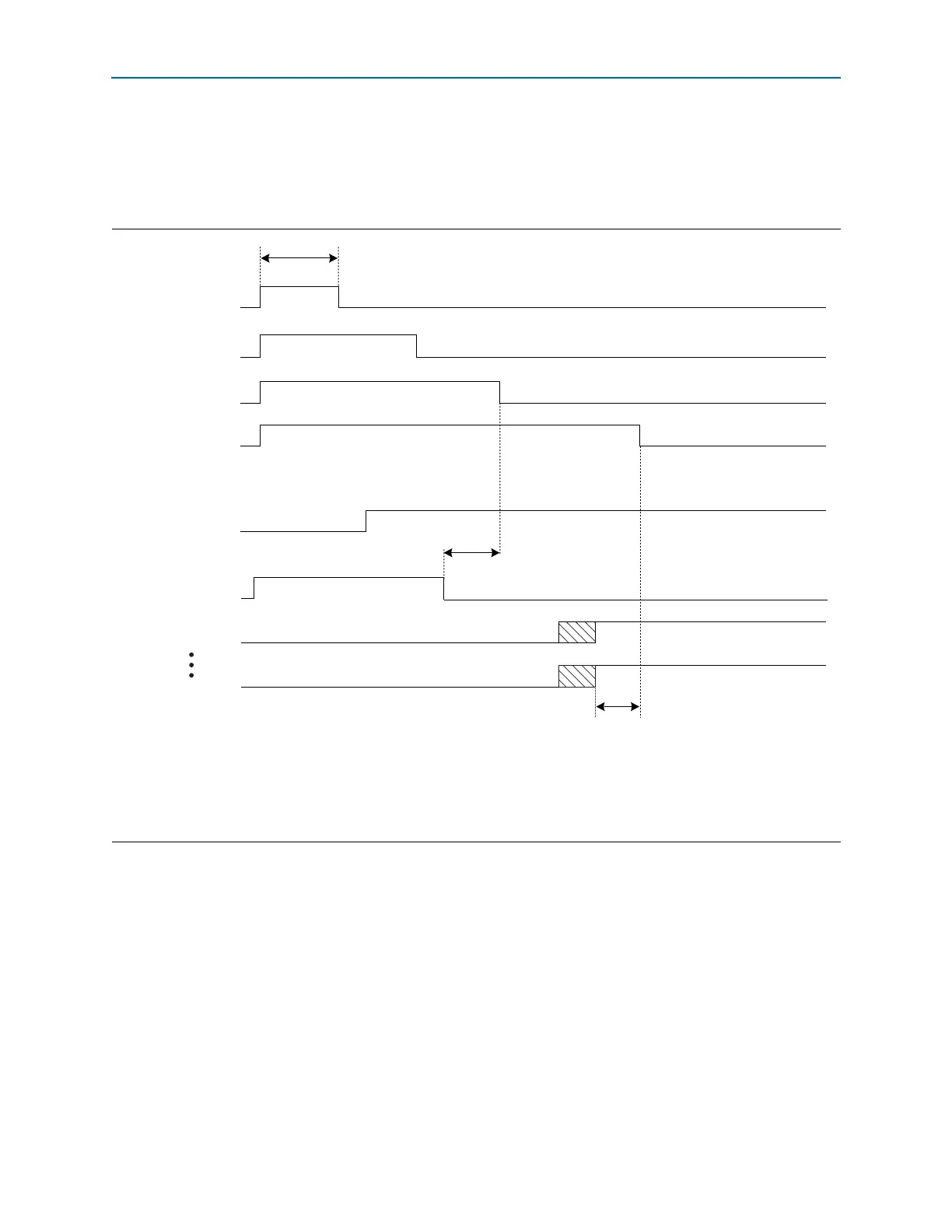
Receiver and Transmitter Channel—Receiver CDR in Automatic Lock Mode
This configuration contains both a transmitter and receiver channel. When the
receiver CDR is in automatic lock mode, use the reset sequence shown in Figure 2–4.
As shown in Figure 2–4, perform the following reset procedure for the receiver CDR
in automatic lock mode configuration:
1. After power up, assert
pll_areset
for a minimum period of 1 s (the time
between markers 1 and 2).
2. Keep the
tx_digitalreset
,
rx_analogreset
, and
rx_digitalreset
signals
asserted during this time period. After you deassert the
pll_areset
signal, the
multipurpose PLL starts locking to the input reference clock.
3. After the multipurpose PLL locks, as indicated by the
pll_locked
signal going
high, deassert the
tx_digitalreset
signal. At this point, the transmitter is ready
for data traffic.
Figure 2–4. Sample Reset Sequence for Bonded Configuration Receiver and Transmitter Channels—Receiver CDR in
Automatic Lock Mode
Notes to Figure 2–4:
(1) The number of
rx_freqlocked[n]
signals depend on the number of channels configured.
n
=number of channels.
(2) For t
LTD_Auto
duration, refer to the Cyclone IV Device Datasheet chapter.
(3) The
busy
signal is asserted and deasserted only during initial power up when offset cancellation occurs. In subsequent reset sequences, the
busy
signal is asserted and deasserted only if there is a read or write operation to the ALTGX_RECONFIG megafunction.
Reset Signals
Output Status Signals
12
3
4
7
7
6
8
5
Two parallel clock cycles
1 µs
pll_areset
tx_digitalreset
rx_analogreset
rx_digitalreset
pll_locked
busy (3)
rx_freqlocked[0]
rx_freqlocked[n] (1)
t
LTD_Auto
(2)