Chapter 2: Cyclone IV Reset Control and Power Down 2–5
Transceiver Reset Sequences
September 2014 Altera Corporation Cyclone IV Device Handbook,
Volume 2
1 The
busy
signal remains low for the first
reconfig_clk
clock cycle. It then gets
asserted from the second
reconfig_clk
clock cycle. Subsequent deassertion of the
busy
signal indicates the completion of the offset cancellation process. This
busy
signal
is required in transceiver reset sequences except for transmitter only channel
configurations. Refer to the reset sequences shown in Figure 2–2 and the associated
references listed in the notes for the figure.
1 Altera strongly recommends adhering to these reset sequences for proper operation of
the Cyclone IV GX transceiver.
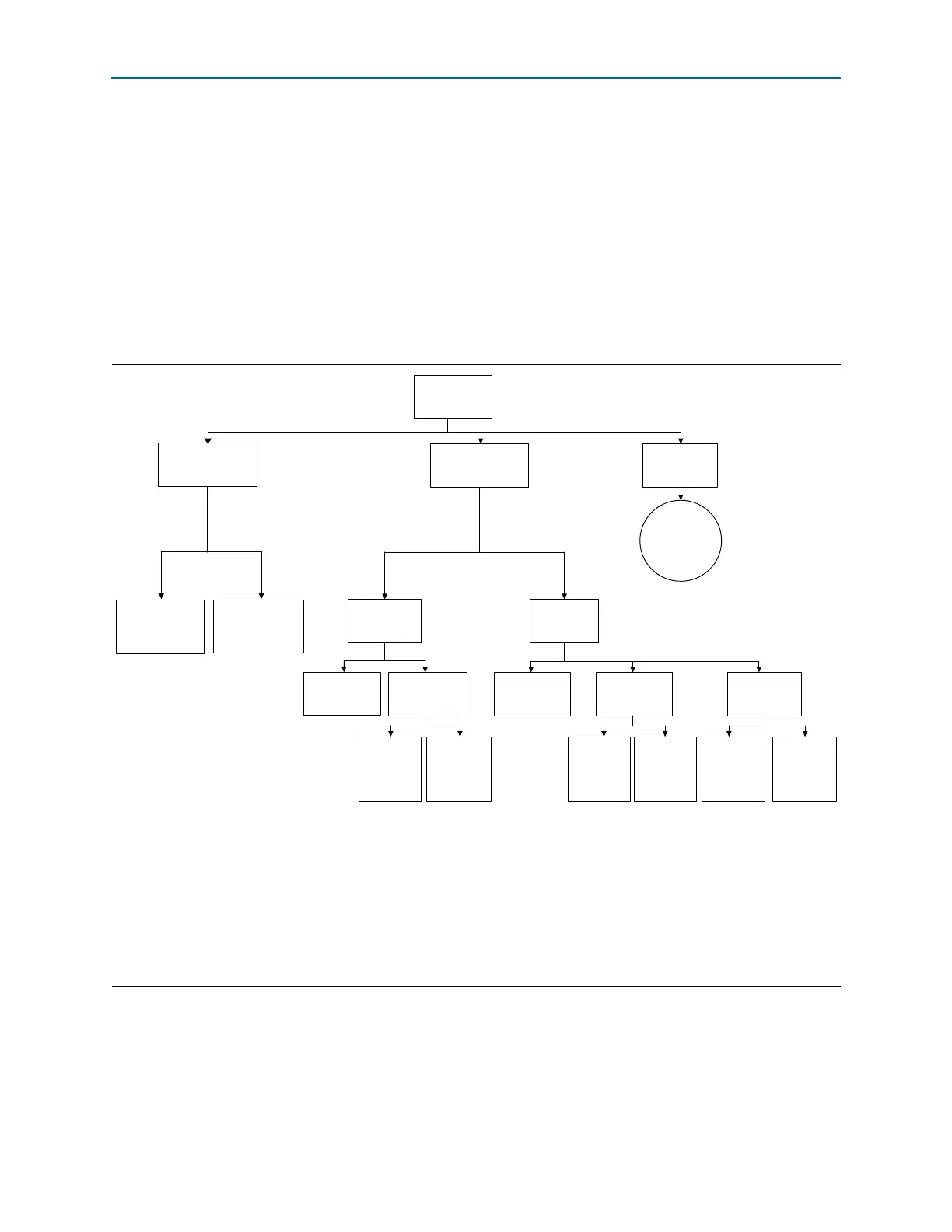
Figure 2–2 shows the transceiver reset sequences for Cyclone IV GX devices.
Figure 2–2. Transceiver Reset Sequences Chart
Notes to Figure 2–2:
(1) Refer to the Timing Diagram in Figure 2–10.
(2) Refer to the Timing Diagram in Figure 2–3.
(3) Refer to the Timing Diagram in Figure 2–4.
(4) Refer to the Timing Diagram in Figure 2–5.
(5) Refer to the Timing Diagram in Figure 2–6.
(6) Refer to the Timing Diagram in Figure 2–7.
(7) Refer to the Timing Diagram in Figure 2–8.
(8) Refer to the Timing Diagram in Figure 2–9.
Tra nsceiver
initialization reset
sequences
All supported
functional modes
except PCI Express (PCIe)
PCI Express
(PIPE)
Initialization/
Compliance and
Normal Operation
Phases (1)
Receiver CDR
in automatic
lock mode
(7)
Receiver CDR
in manual
lock mode
(8)
Receiver CDR
in manual
lock mode
(6)
Receiver CDR
in automatic
lock mode
(5)
‘Receiver Only’
channel
‘Receiver and
Transmitter’
channel
Non-Bonded
Bonded
‘Transmitter Only’
channel (2)
‘Transmitter Only’
channel (2)
‘Receiver and
Transmitter’
channel
Receiver CDR
in automatic
lock mode
(3)
Receiver CDR
in manual
lock mode
(4)
Dynamic Reconfiguration
Reset Sequence
for channel
reconfiguration mode
Reset Sequence
for PLL
reconfiguration mode