S820E UG PN: 10580-00343 Rev. H 3-53
Cable and Antenna Measurements 3-9 Cable and Antenna Analyzer Menus
3-9 Cable and Antenna Analyzer Menus
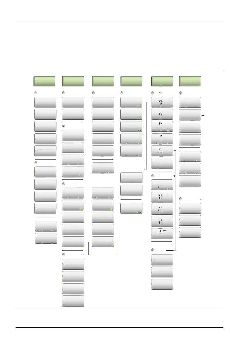
Figure 3-32 and Figure 3-33 show maps of the menus. Menu maps typically
display all possible submenu keys, although some keys may be displayed on
the instrument only under special circumstances (refer to menu descriptions
on the following pages).
Figure 3-32. Menu Keys (1 of 2)
Stop Distance
(D2)
Start Distance
(D1)
Freq/Dist
Frequency
Stop
Frequency
(F2)
Start
Frequency
(F1)
DTF Aid
Distance
Units
top Distanc
D2
TF A
n
t
mft
Cable List
Cable Loss
DTF Setup
Prop Velocity
Windowing
Windowing
Nominal Side
Lobe
rop Velocit
n
ow
ng
Nominal
L
ect
a
Nominal Side
Lobe
Low Side Lobe
Minimum Side
Lobe
DUT Line Type
l
Li
l
L
TF
L
ne
r
m
n
r
rn L
DTF
Return Loss
Cable Loss
VSWR
DTF VSWR
Advanced
vance
Transmission
(Ext. Sensor)
Transmission
(2-Port)
Smith Chart
1-Port Phase
Display Format
Single Dual
Active Display
orma
ingl
ua
ct
ve
sp
a
Top Bottom
Windowing
Nominal Side
Lobe
n
ow
n
ominal
ide
Waveguide
List
Waveguide
Loss
Cutoff Freq
DUT Line Type
avegu
st
avegu
Coax WG
Amplitude
Top
Bottom
Autoscale
Fullscale
Amplitude
Scale Preset
Ref. Impedance
i
t
u
p
L
ne
p
Re
. Impedanc
ȍ ȍ
Smith Chart
only
Marker
Peak Between
M1 & M2
Valley
Between
M1 & M2
M5
On Off
Type
Ref Delta
Marker To
Peak
Display
Mkr + Table
Marker To
Valley
Edit
Select (1-8)
M5
Marker Setup
Marker Search
t
5
ay
Marker Preset
Display
Mkr + Table
sp
ay
r +
k
rac
On Off
Limit
Limit Alarm
On O
Move Active
Limit
Limit Preset
Pass/Fail Msg
rese
r
r
n
imit Al
L
m
t Prese
ass/Fail Ms
1-8
r
m
v
L
m
Upper Lower
Edit Segments
Limit State
O
M
er
imit St
te
Single
Segmented
Limit State
O
Cal Setup
Calibration
Cal Correction
Ma
Measure
Calibration
Thru Update
el
r
li
r
ru
at
n
n
al
orrecti
l In
nterpo
at
on