S820E UG PN: 10580-00343 Rev. H 7-9
Calibration, VNA 7-3 Calibration Setup
Port 1 or Port 2 DUT and Cal Kit
For the most accurate calibrations, you must select the connector of the DUT
that will be attached to Port 1 or Port 2 of the instrument. After you select the
DUT connector, you must then select the desired calibration kit that will be
used for the Port 1 or 2 correction. If you do not select a desired calibration
kit, then the analyzer defaults to one of the built-in kits.
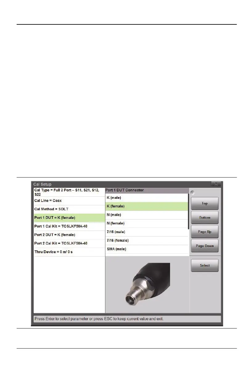
Figure 7-6 shows the selection window for the Port 1 DUT connector. For
easier identification of the DUT connector, a representative picture is shown
for each selection. After a connector is chosen, the Port 1 Cal Kit selection is
updated in order to list only the available calibration kits that are associated
with the selected DUT connector. Figure 7-7 on page 7-10 shows an example
of the selection of calibration kits that are available for the K (female) coaxial
DUT connector.
For each coaxial kit in the list, the values of the Offset Lengths for the Open,
Short, and Thru (if applicable) are listed. The Capacitance and Inductance
values for the Open and Short are also listed, as shown in Figure 7-7. For
waveguide calibration kits, the Cutoff Frequency and the Offset Short 1 and
Short 2 lengths are listed.
Figure 7-6. Selection Window for Port 1 DUT Connector