Home
APRILIA
Motorcycle
RSV4 R
Page 241
APRILIA RSV4 R - Page 241
475 pages
Manual
Save Page as PDF
To Next Page
To Next Page
To Previous Page
To Previous Page
Loading...
•
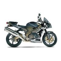
Connect the starter motor, place the
washer and tighten the nut.
•
Place the rubber cap.
•
Tighten the engine oil pressure sensor.
•
Connect the timing sensor.
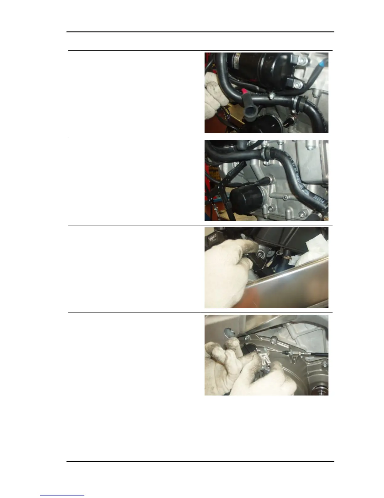
•
Connect the clutch cable.
RSV4 R
Engine from vehicle
ENG VE - 241
240
242
Table of Contents
Main Page
Default Chapter
3
Service Station Manual
3
Product View
4
Index of Topics
5
Coolant
7
Fuel
7
Hot Components
7
Safety Rules
7
Battery Electrolyte and Hydrogen Gas
8
General Precautions and Information
8
Maintenance Rules
8
Used Engine Oil and Transmission Oil
8
Reassembling Components
9
Electric Connectors
9
Components Removal
9
Before Disassembling Components
9
Running-In
10
Chassis and Engine Number
11
Dimensions and Mass
11
Serial Number Location
11
Vehicle Identification
11
Capacities
12
Cylinder
12
Gear Rations
12
Transmission
12
Drive Chain
13
Frame and Suspensions
13
Wheels and Tyres
14
Suspension
14
Brakes
14
Chassis
15
Front Side
15
Cylinder
15
Oil Radiator
15
Tightening Torques
15
Front Fork
16
Front Wheel
17
Steering
17
Front Brake Calliper
18
Front Brake Pump
18
Handlebar and Controls
19
Headlamp
20
Instrument Panel
21
Windshield
21
Clutch Lever
22
Front Mudguard
22
Cooling
23
Central Part
24
Side Stand
24
Table of Contents
25
Fuel Tank
25
Saddle
25
Footpegs
26
Torque Notes
27
Front Chassis
27
Nm (4.42 Lbf Ft)
27
Rear Chassis
28
Torque Notes
28
Front Electrical System
29
Locks
29
Central Electrical System
30
Fairing
31
Back Side
32
Exhaust
32
Rear Wheel
33
Nm (2.95 Lbf Ft)
34
Rear Brake Calliper
34
Rear Brake Pump
34
Nm (5.16 Lbf Ft)
35
Rear Swingarm
35
Rear Shock Absorber
36
License Plate Holder
37
Nm (0.37 Lbf Ft)
37
Nm (1.84 Lbf Ft)
37
Nm (2.21 Lbf Ft)
37
Taillight
37
Tail
38
Helmet Compartment
39
Clutch Cover
40
Engine View
40
Valve Cover
41
Cylinders-Piston
42
Heads
42
Timing System
43
Crankshaft
44
Crankcases
45
Gearbox
46
Clutch
47
Ignition Unit
47
Alternator Cover
48
Lubrication
49
Secondary Air System
49
Recommended Products Chart
50
Water Pump
50
Special Tools
52
Cylinder
54
Maintenance Chart
61
Routine Maintenance Table
61
Front Spark Plugs
62
Rear Spark Plugs
62
Check
63
Engine Oil
63
Replacement
63
Air Filter
65
Engine Oil Filter
65
Checking the Valve Clearance
66
Characteristic
67
Checking the Valve Clearance
67
Front Head
67
Rear Head
67
Front Cylinder Head Valves
68
Cylinder Bank
70
Rear Cylinder Head Valves
74
Cylinder Bank
76
Pad Thicknesses for Adjusting Valve Clearance Correctly
81
Troubleshooting
83
Troubleshooting Procedure if the EFI Warning Light on the Instrument Panel Turns on or if There Is Abnormal Engine Performance
84
The Engine Does Not Start
86
The Engine Does Not Start, the Instrument Panel Turns on
86
Check Control Unit Power Supply
87
Check Fuel Pump
88
Diagnosis Instrument Connection Check
88
Injection Relay 33 Check
89
Protection Relay 19 Check
90
Electrical System
92
Components Arrangement
94
Relay Layout
95
Electrical System Installation
96
Scope and Applicability
96
The Electrical System Consists of the Following Cable Harnesses and Parts
96
Small Parts and Mountings
97
Motorcycle Division
99
Special Checks for the Correct Connection and Laying of Cables
99
Regulator Pre-Fitting
100
Relay and Fall Sensor Mounting Pre-Fitting
100
Headlamp Pre-Fitting
101
Handlebar Controls
102
Instrument Holder Arch Brace and Front Part
102
Left Side
105
Right Side
105
Completion of the Front
106
Radiator Area
107
Demand Sensor Fitting
109
Exhaust Valve Actuator
110
Positioning and Calibration
110
Positioning and Calibration Actuator-Valve
111
Pinion Casing Area
112
Notes for Fitting the Ground Cables
113
Engine-Battery Ground Cable Routing
114
Engine Cable Harness Layout
115
Notes for Engine Cable Harness Fitting
115
Control Unit Mounting Preparation
116
Filter Box Cover and Lower Filter Box Preparation
116
Fitting and Connecting the Secondary Air Solenoid and Fitting the Rubber Manifold with the Clip-On Clamp
117
Fitting the Pipes on the Secondary Air Solenoid
117
Motorised Throttle Body Connection Preparation and Secondary Air Solenoid Fitting
117
H2O Temperature Sensor and Lower Injectors Connection
118
Motorised Throttle Body Fitting
118
H2O Temperature Sensor
119
Coil and Map Sensor Connection
120
Air Temperature Sensor and Upper Injectors Connection
121
Gear Sensor Connection and Oxygen Sensor Cable Harness Routing
121
7Sm Control Unit Fitting and Connection
122
Connectors for Intake Duct Control Unit and Intake Duct Motor
124
Vehicle Connector Fastening
124
Connectors for Intake Duct Control Unit and Intake Duct Motor (if Available)
125
License Plate Frame Pre-Fitting
125
Notes for Fitting the Ground Cable
125
Speed Sensor Pre-Fitting
126
Start-Up Relay Pre-Fitting
126
Rear Swingarm Area
127
Vehicle Cable Harnesses
127
Rear Saddle Mounting Area
128
Rear Stop Switch and Speed Sensor Cable Harness Routing on the Right Side
128
Right Side Saddle Mounting
129
Intake Duct Control Unit and Tank
130
Left Side Saddle Mounting
130
General Wiring Diagram
132
Checks and Inspections
134
Connector Check Procedure
134
General Concepts of Electrical Troubleshooting
134
Continuity Check
135
Ground Connection Check
135
Voltage Check
135
Function
136
Immobiliser
136
Instrument Panel: Errors
136
System Components
136
Dashboard
137
Installing a New Instrument Panel
137
Delete the Error Caused by the Lack of Memory of Key Codes
138
Diagnosis
138
Instrument Panel Errors
138
Search for Minimum and Maximum Mechanical Stops Stored in the Instrument Panel
138
Delete Errors
139
Update
139
Vehicle Servicing Reset
139
Km/Miles
140
Languages
140
Modify Keys
140
Service Warning Light Reset
140
Diagnosis Instrument: Electrical Errors
141
Diagnosis Instrument: Logic Errors
141
Start-Up System Check
141
Level Indicators
142
Main Fuses Distribution
142
Secondary Fuses Distribution
142
Control Unit-Diagnosis
143
Level in Wiring Diagram
143
Location
143
Diagnosis Instrument: Parameters
144
Diagnosis Instrument: Statuses
144
Screen/Example Value with Key Set to on
144
Diagnosis Instrument: Activation
145
EEPROM Error P0601
145
A/D Converter P0607
146
RAM Error P0604
146
ROM Error P0605
146
Stop Lights Relay Error P0610
146
Diagnosis Instrument: Adjustable Parameters
147
Level 2 Safety Reset P0608
147
Safety Engine Stop P0609
147
Saved Data File (for Safety) P0611
147
Battery
148
New Control Unit Activation Procedure and Reprogramming
148
Battery Voltage
149
Battery Voltage P0560
149
Battery Voltage Pre Recovery
149
Operation/Operating Principle
150
Speed Sensor
150
Variable Geometry Intake (if Available)
151
Diagnosis Instrument: Errors
152
Electrical Characteristics
152
Pin out
152
Variable Geometry Intake P0447
152
Engine Rpm Sensor
154
Engine Speed Sensor P0336
155
Twistgrip Position Sensor
155
Blue Lower Connector Throttle Grip Position Sensor-Track a P0150
158
Blue Lower Connector Throttle Grip Position Sensor-Track B P0151
158
White Upper Connector Throttle Grip Position Sensor-Track C P0152
159
White Upper Connector Throttle Grip Position Sensor-Track D P0153
159
Blue Lower Connector Throttle Grip Position (Tracks A-B) P0154
160
Throttle Grip Position P0156
160
White Upper Connector Throttle Grip Position (Tracks C-D) P0155
160
Intake Pressure Sensor
161
Reset Procedure
161
Rear Cylinder Air Pressure Sensor P0105
162
Front Cylinder Air Pressure Sensor P0106
163
Rear Cylinder Air Pressure Sensor P0107
163
Error for Unexpected Air Intake in the Front Cylinder Manifold P0211
164
Rear Cylinder Air Pressure Sensor P0108
164
Estimation Error for Front Cylinder Intake Manifold Pressure P0216
165
Estimation Error for Rear Cylinder Intake Manifold Pressure P0215
165
Engine Temperature Sensor
166
Pressure too Low at Front Cylinder Manifold Error P0218
166
Engine Temperature at Start-Up
167
Engine Temperature Pre Recovery
167
Engine Temperature Sensor P0115
167
Engine Temperature Sensor P0116
168
Air Temperature Pre Recovery
169
Air Temperature Sensor
169
Lambda Correction
171
Lambda Probe
171
Lambda Sensor
171
Lambda Check
172
Lambda Probe Heating
172
Lambda Probe P0130
172
Lambda Probe Heating P0135
173
Lower Injectors Key
174
Lower Injector
175
Lower Injector Cylinder 1 P0201
176
Lower Injector Cylinder 2 P0202
177
Lower Injector Cylinder 3 P0203
177
Lower Injector Cylinder 4 P0204
178
Upper Injector Function
179
Upper Injectors Key
179
Lower Injector Cylinder 1
180
Upper Injector Cylinder 2, 3, 4
180
Upper Injector Cylinder 1 P0205
181
Upper Injector Cylinder 2 P0206
181
Upper Injector Cylinder 3 P0207
182
Upper Injector Cylinder 4 P0208
182
Fuel Pump
183
Coil
184
Fuel Pump Relay Control P0230
184
Example Value with Engine on
185
Example Value with Key on
185
Coil 1 P0351
186
Coil 2 P0352
186
Coil 3 P0353
187
Coil 4 P0354
187
Throttle Body
188
Front and Rear Cylinder Throttle Correction
188
Front Throttle Potentiometer 1 (Degrees)
188
Throttle Check and Throttle Grip Sensor (Demand)
188
Front and Rear Throttle Potentiometer 1, 2 (Voltage)
189
Front and Rear Throttle Potentiometer 2 (Degrees)
189
Rear Throttle Potentiometer 1 (Degrees)
189
Front and Rear Cylinders Throttle Limp Home Position
190
Front and Rear Throttle Automatic Self-Acquisition
190
Front and Rear Throttle Lower Position
190
Potentiometer 1 Sensor, Rear Throttle Position P0120
191
Potentiometer 2 Sensor, Front Throttle Position P0127
192
Rear Throttle Control Circuit P0166
192
Front Throttle Control Circuit P0186
193
Potentiometer 1 Sensor, Rear Throttle Position P0121
194
Potentiometer 2 Sensor, Rear Throttle Position P0123
194
Rear Throttle Position Potentiometer P0124
194
Front Throttle Position Potentiometer P0129
195
Potentiometer 1 Sensor, Front Throttle Position P0126
195
Potentiometer 2 Sensor, Front Throttle Position P0128
195
Detection of the Rear Throttle Recovery Conditions (Air Temp., Water Temp.) P0163
196
Rear Throttle Limp Home Self-Acquisition P0160
196
Rear Throttle Mechanical Springs Self-Acquisition P0161
196
Rear Throttle Minimum Mechanical Position Self-Acquisition P0162
196
Front Throttle Limp Home Self-Acquisition P0180
197
Front Throttle Mechanical Springs Self-Acquisition P0181
197
Rear Throttle Position Error P0167
197
Rear Throttle Power Supply Voltage During Self-Learning P0164
197
Detection of the Front Throttle Recovery Conditions (Air Temp., Water Temp.) P0183
198
Front Throttle Minimum Mechanical Position Self-Acquisition P0182
198
Front Throttle Position Error P0187
198
Front Throttle Power Supply Voltage During Self-Learning P0184
198
DSB 07: Oil Pressure Sensor
199
Engine Oil Pressure Sensor
199
DSB 08: Oil Pressure
200
Neutral Sensor
200
Gear Sensor P0461
201
Clutch Lever Sensor
202
Side Stand Sensor
203
Bank Angle Sensor
204
Fall Sensor: Normal/Tip over
204
Electric Fan Circuit
205
Cooling Fan Relay P0480
206
SAS Valve Actuator
207
Secondary Air Valve Control P0446
207
Secondary Air Valve Duty Cycle
207
Run/Stop Switch
208
Butterfly Valve in Exhaust
209
Exhaust Valve Stop Research P0191
210
Exhaust Valve Engine P0192
211
Exhaust Valve Position P0190
212
Exhaust Valve Potentiometer P0193
212
Connectors
214
Exhaust Throttle Valve Calibration
214
Ecu
215
Engine Pinout Key
215
Vehicle Pinout Key
217
Engine-Vehicle Connector Pinout Key
218
Grey-Bodied Instrument Panel Pinout Key
219
Black-Bodied Instrument Panel Pinout Key
220
Can Line
221
Can Protocol (Cont. Network Area)
221
Can System Advantages
221
Can Line "Mute Node" U1601
222
Can Line Without Signals U1602
222
Can Line Towards Instrument Panel U1701
223
Engine from Vehicle
224
Position the Vehicle as Described
225
Proceed as Follows to Remove from the Chassis
225
Vehicle Preparation
225
Removing the Engine from the Vehicle
226
Installing the Engine to the Vehicle
234
Centring the Engine on the Chassis
235
Engine Retainer
236
Working on the Left Side
236
Working on the Right Side
236
Engine
243
Combustion Angle
244
Key
244
Diagram
245
Removing the Gearbox
245
Disassembling the Gearbox
247
Gearbox Shafts
247
Desmodromic Gearbox Control Rod Drum Roller Cage, Alternator Side
248
Checking the Desmodromic Drum
249
Checking the Primary Shaft
249
Checking the Secondary Shaft
249
Assembling the Gearbox
250
Checking the Forks
250
Removing the Gear Selector
253
Gearbox Control Rod Oil Seal and Roller Cage, Spacer
254
Gearbox Control Rod Roller Cage, Clutch Side
254
Checking the Gear Selector
255
Reassembling the Gear Selector
255
Removing the Starter Motor
255
Removing the Idle Gear
256
Generator Side
257
Magneto Flywheel Removal
258
Removing the Flywheel Cover
258
Inspecting the Cover Components
259
Installing the Flywheel
259
Flywheel Cover Installation
260
Clutch Side
261
Disassembling the Clutch
262
Removing the Clutch Cover
262
Checking the Clutch Plates
265
Checking the Clutch Housing
266
Checking the Clutch Hub
266
Checking the Pusher Plate
266
Assembling the Clutch
267
Checking the Springs
267
Installing the Clutch Cover
272
Head Cover Removal
275
Removing Camshafts
275
Camshaft Lobes
278
Camshaft Toothed Wheel Check
278
Inspecting Camshafts
278
Installing Camshafts
279
Maximum Camshaft Axial Clearance (Intake/Exhaust)
279
Front Head Removal
282
Front Head Check
286
Front Head Fitting
287
Rear Head Removal
299
Rear Head Check
303
Rear Head Fitting
303
Valve Removal
309
Valve Check
310
Valve Installation
312
Crankcase
314
Balancing Countershaft Removal
316
Balancing Countershaft Fitting
317
Main Transmission Gear Removal
318
Installing the Primary Drive Gear
320
Crankcase Opening
321
Removing Connecting Rods-Pistons
323
Crankshaft Removal
324
Balancing Countershaft Check
325
Bushing Removal
325
Countershaft Bushings
325
Crankshaft Check
325
Connecting Rod Check
326
Inspecting Pistons
326
Selecting Connecting Rods
327
Bushing Selection
328
Crankcase Category
328
Crankshaft Bushings
328
Crankshaft Bushings with Non Removable Reels
329
Crankshaft Bushings with Removable Reels
329
Crankshaft Categories with Non Removable Reels
329
Crankshaft Categories with Removable Reels
329
Crankshaft Bushing Replacement Procedure
330
Crankshaft Bushings-Connecting Rods
330
Bushing Fitting
331
Crankshaft Fitting
333
Installing Connecting Rods-Pistons
335
Crankcase Closing
337
Thermal Group
340
Oil Pump
341
Removing
341
Installing
343
Blow-By
346
Removing the Oil Sump
346
SAS Valve
347
Inspecting the One-Way Valve
348
Power Supply
349
Injection
350
Operating Logic
352
Ride by Wire
352
The Marelli Control Unit Performs the Following Functions
352
Lower Injectors
353
Removing the Injector
353
Removing the Throttle Body
354
Upper Injectors
354
Checking the Throttle Body
355
Electric Motor
356
Installing the Throttle Body
356
Stepper Motor
356
Cylinders Synchronisation
358
Suspensions
360
Removing the Front Wheel
361
Checking the Front Wheel
362
Front Wheel Bearings
362
Radial and Axial Clearance Check
363
Rotation Check
363
Handlebar
364
Front Fork
365
Adjustment
366
Front Fork-Racing Adjustment Range (Track Use Only)
366
Front Fork-Standard Setting (for Road Use Only)
366
Removing the Fork Legs
367
Draining Oil
368
Disassembling the Fork
370
Checking the Components
373
Reassembling the Fork
375
Filling Oil
378
Adjusting
380
Steering Damper
380
Steering Bearing
381
Adjusting Play
382
Removing the Rear Wheel
385
Checking the Rear Wheel
388
Rear Wheel Bearings
388
Rear Wheel Gaskets
388
Final Transmission Unit Bearings
389
Rear Wheel Rim
389
Flexible Coupling
390
Sprocket
390
To Check
390
Working from the Wheel Right Side
390
Final Transmission Unit-Bearing Removal
391
Wash All the Parts with Clean Detergent
391
Working from the Wheel Left Side
391
Shock Absorbers
393
Rear Shock Absorber-Racing Adjustment Range (Track Use Only)
394
Rear Shock Absorber-Standard Adjustment (for Road Use Only)
394
Linkages
396
Swinging Arm
400
Checking
403
Swingarm Bearings
404
Swingarm Pin
404
Swingarm Seals
404
To Check Clearance
407
Checking the Chain, the Pinion and the Sprocket for Wear
408
If You Need to Adjust Chain Tension after the Check
408
Chain Sliders
409
Cleaning and Lubrication
409
Stand
410
Side Stand
411
Removing the Tail Pipe
413
Removing the Catalytic Converter
414
Removing the Exhaust Manifold
414
Rear Exhaust Manifolds
416
Removing the Exhaust Throttle Valve
416
Engine Oil Cooler
417
Braking System
420
Rear Brake Disc
422
Disc Inspection
423
Front Brake Disc
423
Front Brake Pads
425
Rear Brake Pads
426
Bleeding the Braking System
428
Cooling System
432
Circuit Diagram
433
System Type
433
Electric Fan
435
Coolant Replacement
436
Filling
436
Water Pump
437
Removing the Radiator
439
Bodywork
442
Driving Mirrors
451
Instrument Panel
452
Headlight Fairing
453
Side Fairings
454
Central Underfairing
456
Fairing Mounting Panels
456
Lower Side Fairings
456
Lateral Underfairings
457
Air Box
458
Filter Box Cover Removal
458
Filter Box Base
459
Lower Cowl
460
Rear Mudguard
460
Fuel Tank
461
Front Mudguard
463
Instrument Cluster Support
463
Fitting
464
Radiator Cover
466
Side Air Deflectors
467
Pre-Delivery
468
Aesthetic Inspection
469
Carry out the Listed Checks before Delivering the Vehicle
469
Tightening Torques Inspection
469
Levels Check
470
Road Test
470
Functional Inspection
471
Specific Operations for the Vehicle
471
Static Test
471
Operations Required to Render Vehicle Compliant with Two Seater Type Approval
472
Index
474
Related product manuals
APRILIA RSV4 RR
574 pages
APRILIA RSV4 FACTORY
181 pages
APRILIA RSV4 RR 2017
558 pages
APRILIA RSV4 RF 2017
558 pages
APRILIA RSV4 1100 Factory
549 pages
APRILIA RSV4 FACTORY-R - 2009
249 pages
APRILIA RSV4 1100 Factory 2021
500 pages
APRILIA RSV4 Factory a-PRC 2009
521 pages
APRILIA RSV4 FACTORY-R - 10-2010
213 pages
APRILIA RSV 1000 R
190 pages
APRILIA RSV 1000 TUONO R
120 pages
APRILIA RSV MILLE R TUONO - 2002
154 pages