9-24 Parameters ECODRIVE03-FL*-04VRS
DOK-ECODR3-FL*-04VRS**-FK01-EN-P
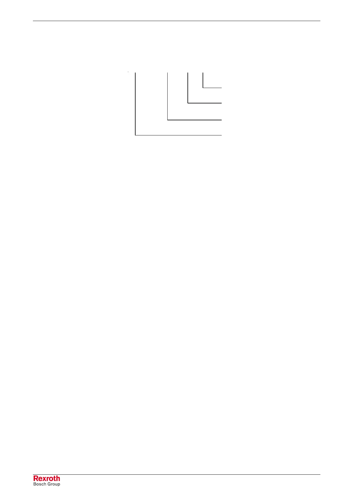
AA11 Tool Wear
Q3.00 M8.02 8 630
Number of the first variable of the
"Counter" variable field
Number of output bits to be counted
Marker Byte, degree of wear
reached M2-M4, M8
Output Byte
M2, M3, M4
DKC21.3: Q0.00.4-Q0.01.3
DKC 3.3 : Q2.02.0-Q2.05.7
EMD: Q3.00.0-Q3.03.7
00.00.0 = Function Deactivated
The wear on a tool, corresponding with a defined number of times the tool
is activated, shall be output.
The switching operations (0 to 1 transition) of the output bits in the output
byte recorded here, are counted. For each output bit, the corresponding
bit of the marker group with the same number is assigned. In the variable
field, the number of counters is defined along with the number of outputs.
After reaching the command piece count, the corresponding marker bit is
set.
Vnnn Å Output bit 0 (Command number of times activated)
Vnnn+1 Å Output bit 0 (Actual number of times activated)
. . .
Vnnn +14 Å Output bit 7 (Command number of times activated)
Vnnn +1+14 Å Output bit 7 (Actual number of times activated)
After reaching the command piece count, the corresponding marker bit is
set and the counter continues to count. The markers and the variables
with the actual piece count must be cleared by the user.
The output byte can only be changed using Command APZ.
To do this, the function in Parameter AA11 must be activated, otherwise
the error message "F-02 24 – APZ not allowed" is issued.
 Loading...


