ECODRIVE03-FL*-04VRS Command Communications 11-1
DOK-ECODR3-FL*-04VRS**-FK01-EN-P
11 Command Communications
11.1 Parallel Interface
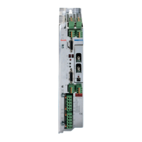
DKC21.3
Three connectors serve as the parallel interface.
X1, X3 and X210
See also the Project Planning Manual and Section 13.
Diagnostic LED for Parallel Interface
For diagnosing the parallel interface, four LEDs are available on the front
of the card. These LEDs signal the status of the control.
H211 H210 H213 Definition
green off - - Status Diagnostic
red green - - Warnings E-01xx
red orange - - Error Message F-02xx
red red - - Error Message F-03xx
- - - - off Command communications not
working
any any orange blinking Initialization active
any any green blinking System is working
Fig. 11-1: Diagnostic LED for Parallel Interface
The LEDs H212, H214 and H215 have no function
Note: If all 6 LEDs turn orange approximately 10 seconds after start-
up, the parallel interface is not working. The firmware on the
programming module is either a wrong or defective version.

 Loading...


