OPERATOR’S MANUAL
CMA-9000 FLIGHT MANAGEMENT SYSTEM
NAME SYMBOL APPLICABLE
MODE(S)
REMARKS
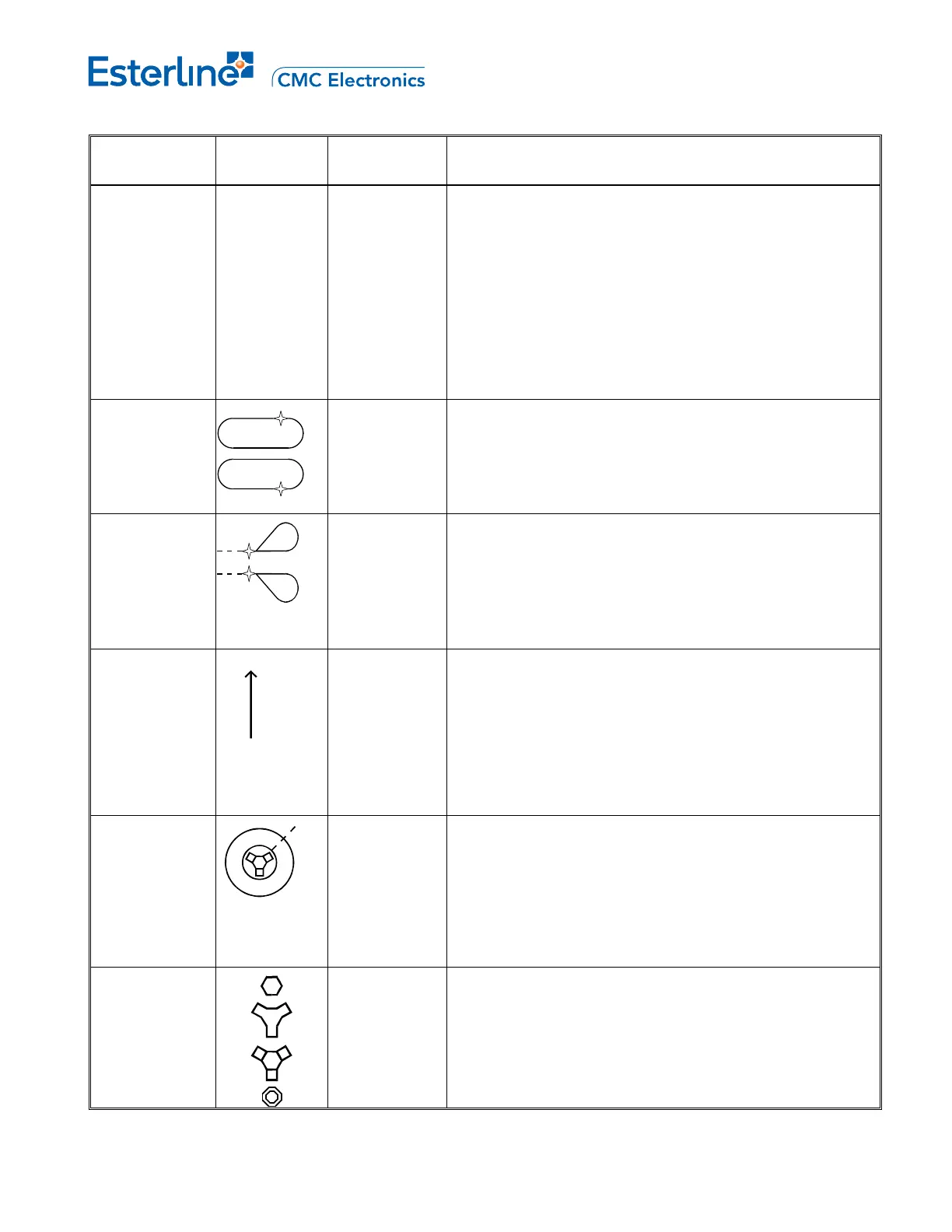
VERTICAL
ALTITUDE
PROFILE
POINT
and
IDENTIFIER
(G)
O T/C
O S/C
O T/D
O E/D
O D
MAP
MAP CTR
PLAN
Represents an FMS calculated point and is labeled on the
flight plan path as T/C (top-of-climb), T/D (top-of-descent),
S/C (step climb), E/D (end-of-descent) and D (deceleration).
HOLDING
PATTERN
ACTIVE (M)
MODIFICATIO
N (W)
INACTIVE (C ))
MAP
MAP CTR
PLAN
A fixed size holding pattern is displayed when selected or an
instrument procedure with a holding pattern is selected into
the route. Actual holding pattern size is displayed when
holding waypoint is active and HSI range 80 nm or less.
PROCEDURE
TURN
ACTIVE (M)
MODIFICATIO
N (W)
INACTIVE (C))
MAP
MAP CTR
PLAN
A fixed size procedure turn is displayed when an instrument
approach procedure with a procedure turn is selected into
route. Actual procedure turn size is displayed when
procedure turn is active and HSI range is 40 or less.
NORTH
POINTER
(G)
PLAN Indicates map background is oriented and referenced to true
north.
SELECTED
REFERENCE
POINT and
BEARING
DISTANCE
INFORMATION
(G)
MAP
MAP CTR
PLAN
Displays the reference point selected on the FIX page.
Bearing and/or distance from the Fix are displayed with
dashes.
VOR (C,G)
DME/TACAN
(C,G)
VORTAC (C,G)
NDB (M)
MAP
MAP CTR
When NAVAID P/B is ON, all appropriate navaids in range
appear in addition to those navaids which are standard or
active. Tuned nav aids are displayed regardless of the
NAVAID P/B and appear green.
When HSI is 80, 160, 320 or 640 only high altitude navaids
are displayed. Otherwise, both high and low altitude
navaids are displayed.
N
ABC
Page C-7
August 17, 2010