GE HEALTHCARE
DIRECTION FC091194, REVISION 11 VIVID 7 SERVICE MANUAL
Chapter 5 - Components and Functions (Theory) 5 - 15
5-3-10-2 Location in the Unit
5-3-10-3 Input DC Voltages
NOTICE
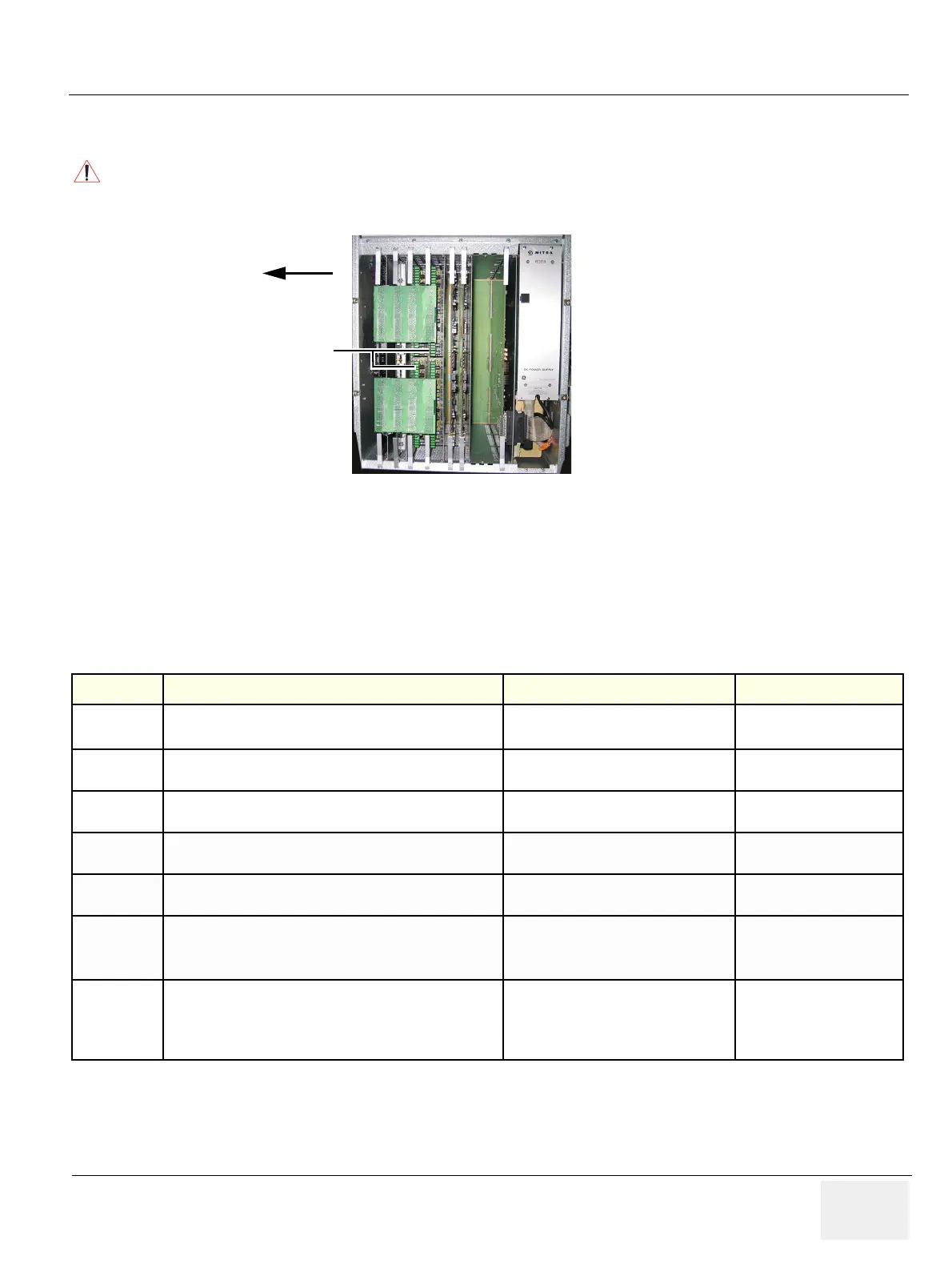
Please be careful about the positions when replacing the TX card and the RX card. The position of the
two cards are interchanged between FEP1 and FEP2.
Figure 5-11 TX128-5 Board: Location in Unit
Table 5-4 Input, DC Voltages
INPUT DESCRIPTION CONNECTOR-PIN# CONNECTION FROM
+6 Va
DC voltage, distributed via Motherboard (Backplane).
The “a” indicates that this voltage is used for analog circuits.
J7-A22,B22,C22,D22,E22
DC Power Supply >
Backplane
+15 Va DC voltage, distributed via Motherboard (Backplane).
J6-C20,D20,E20
J7-A18,A19,A20
DC Power Supply >
Backplane
-5 Va DC voltage, distributed via Motherboard (Backplane). J6-C3,D3,E3
DC Power Supply >
Backplane
-15 V DC voltage, distributed via Motherboard (Backplane). J6-C1,D1,E1
DC Power Supply >
Backplane
GND Ground is distributed via Motherboard (Backplane).
DC Power Supply >
Backplane
HV1
TX Voltage 1
Voltage can be programmed to vary from +/- 2.5 V to +/- 95V
Used to drive the transmitters in 2D Mode and M Mode
HV1N: J6-A15
HV1P: J6-A24
TX Power Supply >
Backplane
HV2
TX voltage 2
Voltage can be programmed to vary from +/- 2,5 V to +/- 95V
Used to drive the transmitters in Doppler (CW/PW) mode
and in Color Flow Mapping (CFM) mode
HV2N: J6-A18
HV2P: J6-A21
TX Power Supply >
Backplane
FEP2 with two TX boards
FRONT OF
SCANNER
TX128
BOARDS (2X)

 Loading...


