GE HEALTHCARE
DIRECTION FC091194, REVISION 11 VIVID 7 SERVICE MANUAL
Chapter 6 - Service Adjustments 6 - 7
6-7-3 Front-End Alignment Procedure
1.) Disconnect all connected probes.
2.) Turn on the Vivid 7.
3.) Press CONFIG
(F2) and log on as adm, see 4-2-4 "Log On to the System as ‘ADM’" on page 4-12.
4.) Select System
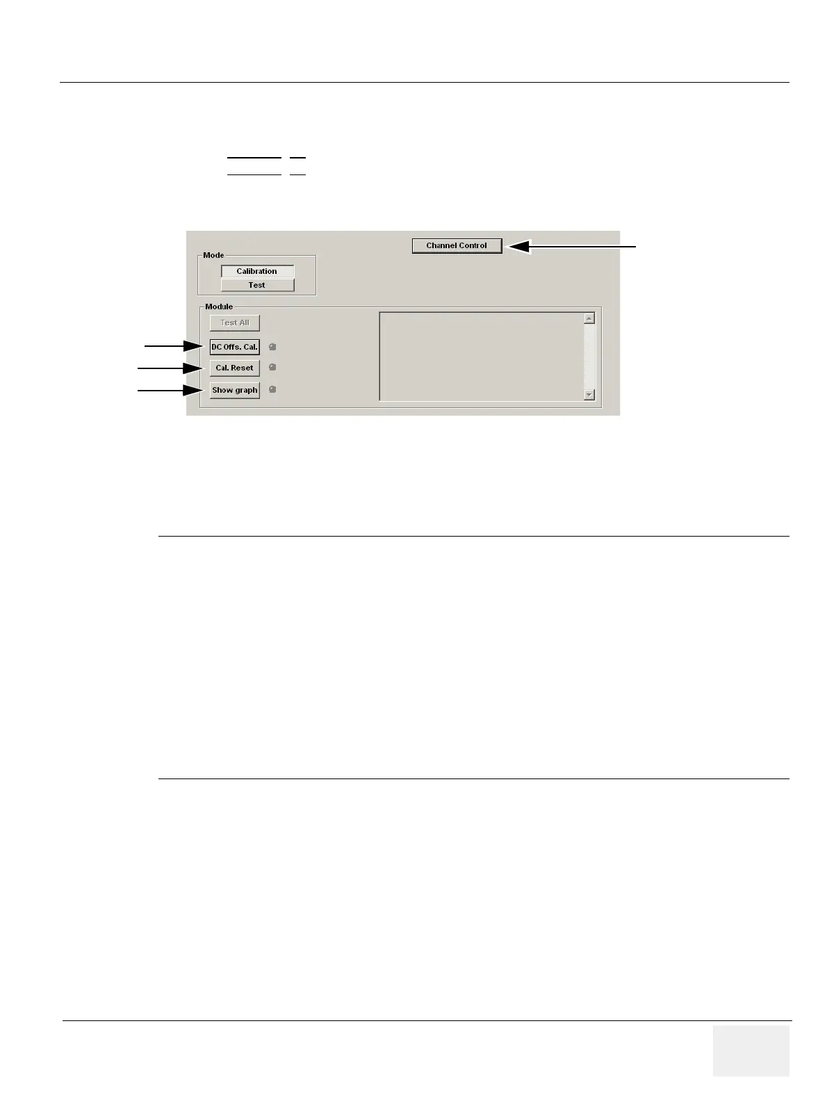
5.) Select DC Offs. Cal to start the DC Offset calibration of the Beam Formers (Front-End Alignment).
6.) Wait for the calibration to take place.
Front-End Alignment Description
- Each A/D converter will get 0V input (by setting ATGC to minimum).
- One by one channel will be digitized and the result put in the IQ buffer on the RFT board.
- The BEP will then read the IQ buffer and computes a value per channel. These computed
values are compared to an upper/lower limit.
- If all read values are ok, the message PASSED will appear. If values exceeding the limits are
read, the system will prompt you with FAILED and a message will tell you which BF board is
bad.
- The resulting offsets for each channel are stored in a file on the Back-End Processor’s hard
disk.
- The values can be plotted in a diagram Show graph).
7.) When finished, select Show Graph.
Wavy line signifies system has been calibrated. See Figure 6-3 "DC Calibration of the Beam Former
AD-converters Passed" on page 6-8.
A Straight line signifies that the system has not been calibrated and can be the cause of image
quality issues.
Figure 6-2 Calibration Dialog
Channel Control
DC Offs. Cal
Cal. Reset
Show graph

 Loading...


