GE HEALTHCARE
DIRECTION FC091194, REVISION 11 VIVID 7 SERVICE MANUAL
5 - 102 Section 5-5 - Patient I/O (Physio)
5-5-3 Patient I/O - Inputs
• ECG / Respiration
• Phono (from a phono heart microphone)
• Two Analog Inputs:
-AUX1
- AUX2 (Pulse/Pressure)
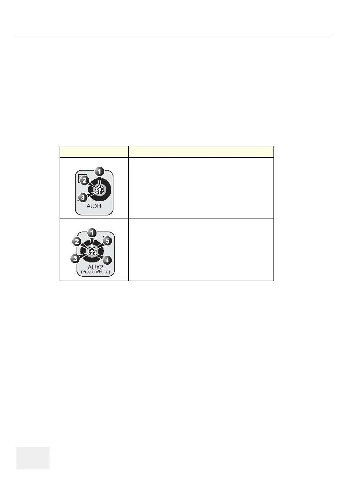
5-5-3-1 Pinout for the AUX Connectors
The pinout for the AUX connectors is described in the table below:
Both AUX1 and AUX2 are by default 1 Vpp (Volt peak-peak) inputs with a max frequency of 300 Hz.
The inputs are differential. For a single ended sensor signal, the pin 1 (input -) should be connected to
the GND (ground) of the sensor.
AUX2 has a programmable high gain mode with a maximum input signal of 300 mVpp (millivolt peak-
peak).
5-5-4 Patient I/O - Outputs
• Serial Trace Data (SCSI bus) to PC2IO or DGIO.
(This version is used on all BEP1, BEP-2.x, BEP3.0 and BEP4 used as replacement for BEP2.x.)
• Starting from the introduction of BT’05 and BEP3.2, a new Patient I/O module with USB-1.1
interface is used.
• Starting from BT’06 and BEP4.2, two Patient I/O models are supported:
- Patient I/O module with USB-1.1 interface
- Patient I/O module with USB-2.0 interface
Table 5-68 Pinout for the AUX Connectors
CONNECTOR SIGNAL NAME
AUX1
1.) pin 1: input -
2.) pin 2: input +
3.) pin 3: gnd
AUX2
1.) pin 1: input -
2.) pin 2: input +
3.) pin 3: gnd
4.) pin 4: nasal sensor 1
5.) pin 5: nasal sensor 2