GE HEALTHCARE
DIRECTION FC091194, REVISION 11 VIVID 7 SERVICE MANUAL
Chapter 5 - Components and Functions (Theory) 5 - 45
5-3-17 Digital Signal Processors Subsystem In Units with FEP1
NOTE: The Digital Signal Processors Subsystem, as described here, is only used in Front-End Rack
version 1 (FEP1).
In units with Front-End Rack version 2 (FEP2), the RFI board plus software on the BEP replaces
the functionality of these boards, see: 5-3-21 "Radio Frequency Interface Board, RFI" on
page 5-61.
5-3-17-1 General Description
The digitized signals from the Beam Formers, are connected to the Digital Signal Processing modules.
These Digital Signal Processors together with software on the BEP, performs the adequate signal
conditioning for the different data types; Tissue, Doppler and Color Flow.
5-3-17-1-1 Tissue and Doppler Signal Processing
A.) On units with FEP1, the following boards perform the signal processing for Tissue and Doppler
signals,
- RF & Tissue Processor board (RFT)
- Spectrum Doppler Processor board (SDP).
B.) On units with FEP2, a new card, the Radio Frequency Interface (RFI) board (together with software
on the BEP), replaces the functionality of the RFT and SDP cards and perform the signal processing
for Tissue and Doppler signals.
5-3-17-1-2 Color Flow Processing
Color Flow processing is done by software on the Back-End Processor.
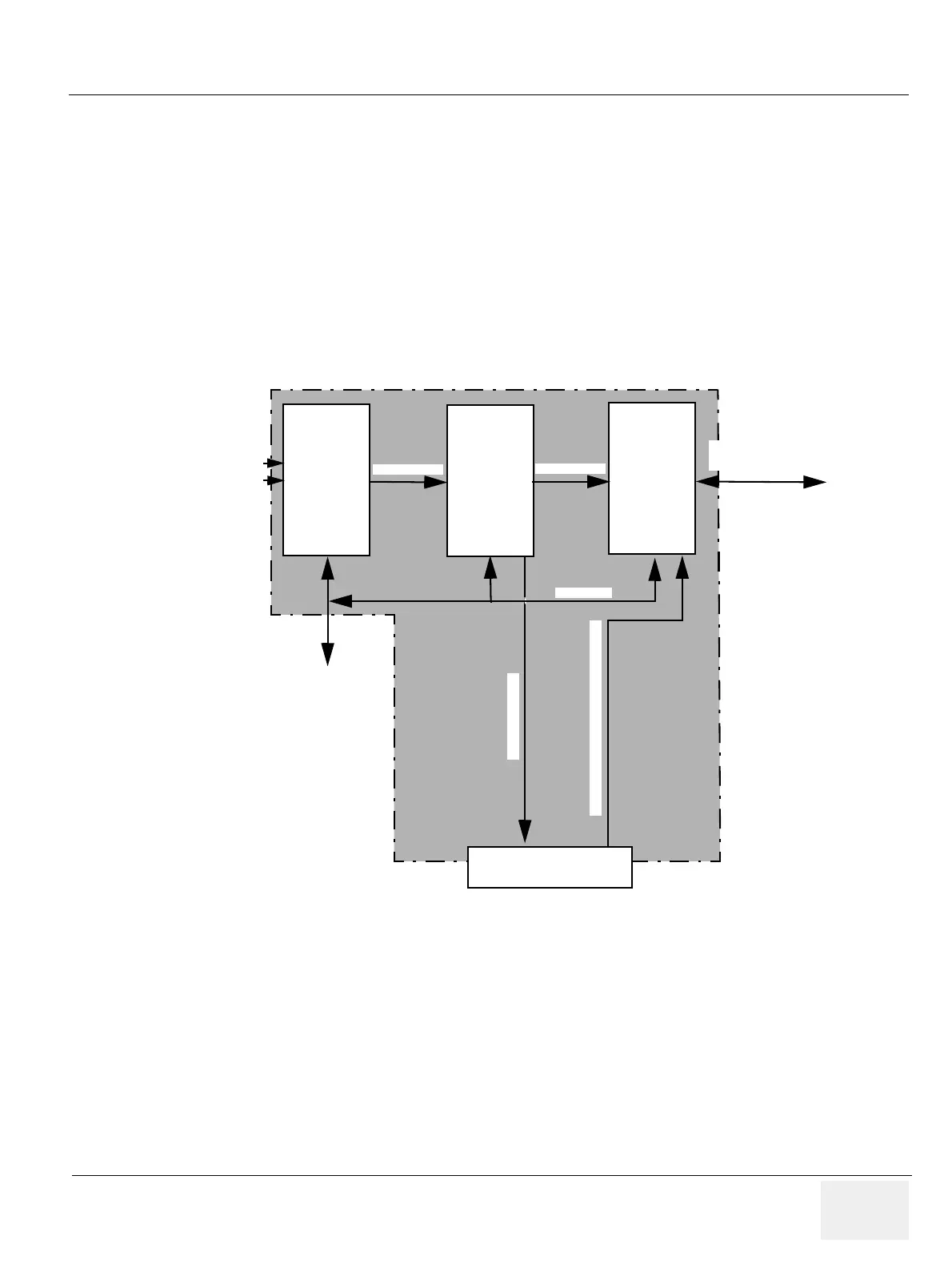
Figure 5-31 Digital Signal Processing
RFT - Radio
Frequency &
Tissue
SDP -
Spectral
Doppler
IMP -
Image Port
Motherboard connector
to Internal I/O module
VME-bus
Doppler Audio
S-Video/CVideo replay (from VCR)
To/From
FEC
Digitized received
ultrasound signals
from Beam Former
To Back-End
Processor
PC2IP bus
(Digital Video Data)
PipeLink
PipeLink