GE HEALTHCARE
DIRECTION FC091194, REVISION 11 VIVID 7 SERVICE MANUAL
8 - 84 Section 8-11 - AC Power Replacement Procedure
8-11-5 AC Power Installation Procedure
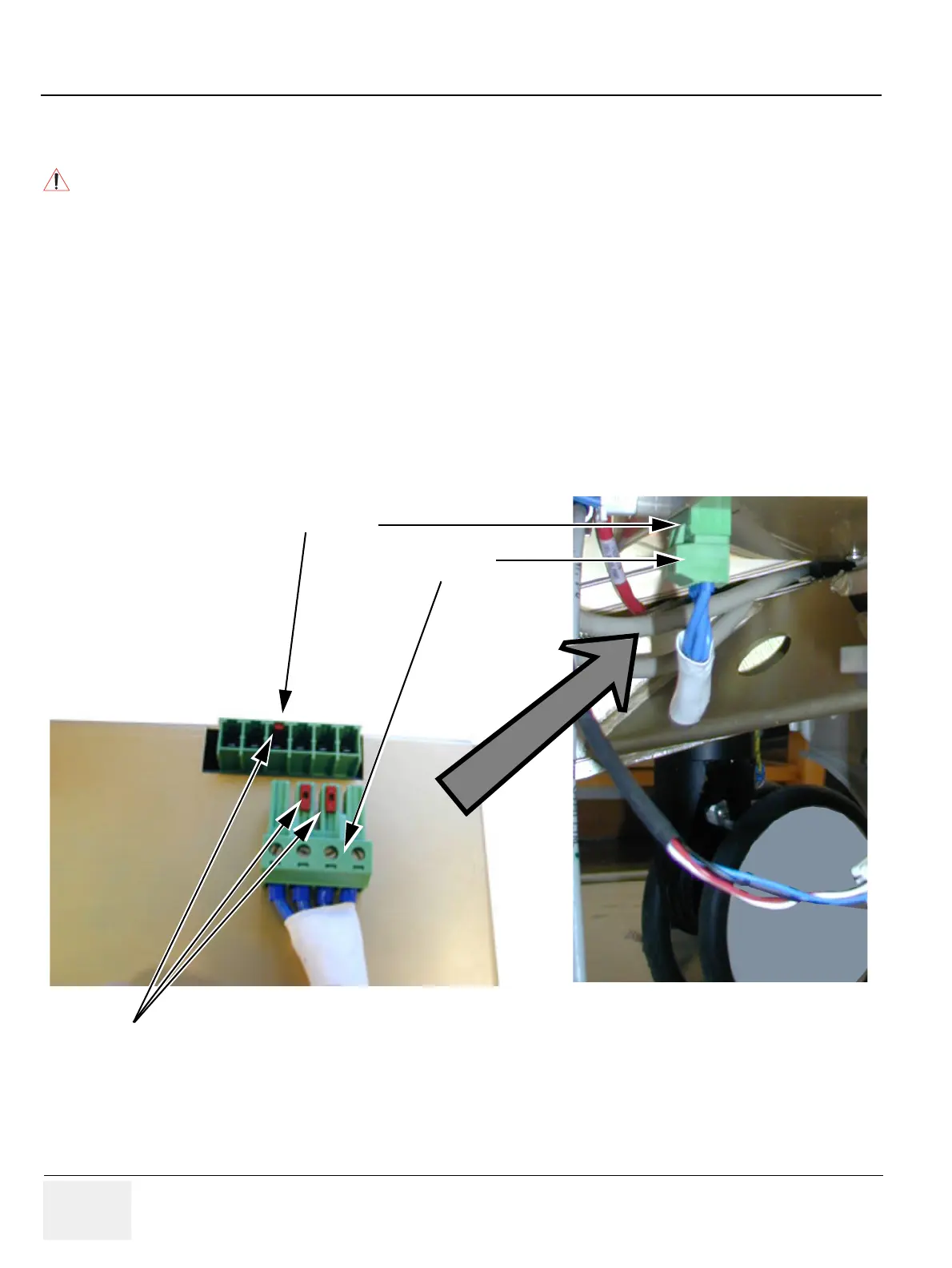
1.) Connect the cables. You may need to leave the Speed Control cable and the Fan cable
unconnected until you have fastened the unit. Input Voltage connector and socket are coded to
prevent mistakes. In 115V system the connector matches one end of the 8-holed socket. In 230V
system it matches the other end of the socket. Figure 8-81 is on a 230V system, and the connector
can only be plugged in the right end of the socket.
2.) Fasten AC Power Module for correct Voltage and connect the remaining cables.
3.) Install Lower Rear Cover, see "Lower Rear Cover Installation Procedure" on page 8-10.
4.) Install Filter Cover, see "Upper Rear Cover Installation Procedure" on page 8-6.
5.) Install Right Side Cover, see "Side Covers Installation Procedure" on page 8-5.
6.) Do functional check-out, see Chapter 4.
DANGER
Before installing a replacement unit, verify that the power selector on the AC
Power Module is set to the correct voltage for the peripherals used on the
system.
Figure 8-81 Input Voltage connector/socket
4 pin connector
Red blocks prevents
wrong connections
P5:
6 holed socket