Chapter 4 Installation
4-1-3
When mounting multiple inverters in an enclosure with a ventilation fan, carefully
design the layout of the ventilation fan, air intake port, and inverters. An
inappropriate layout will reduce the inverter-cooling effect and raise the ambient
temperature. Pay close attention so that the ambient temperature of the inverter is
within the allowable operating temperature range.
If a ventilation fan is located directly above the inverter, dust or dirt may drop on it.
To prevent this, move the inverter horizontally to a suitable position.
Calorific value of the inverter
For the calorific value of the inverter, refer to the power losses listed in
https://ecodesign.hitachi-industrial.eu/.
(1) By accessing the above URL, the "ENERGY EFFICIENCY CERTIFICATES" page is displayed.
(2) Select WJ-C1 from the above-mentioned web site. WJ-C1 model list appears.
(3) Click the model for which you want to know the power loss. The following PDF file will be
displayed with the loss of each model.
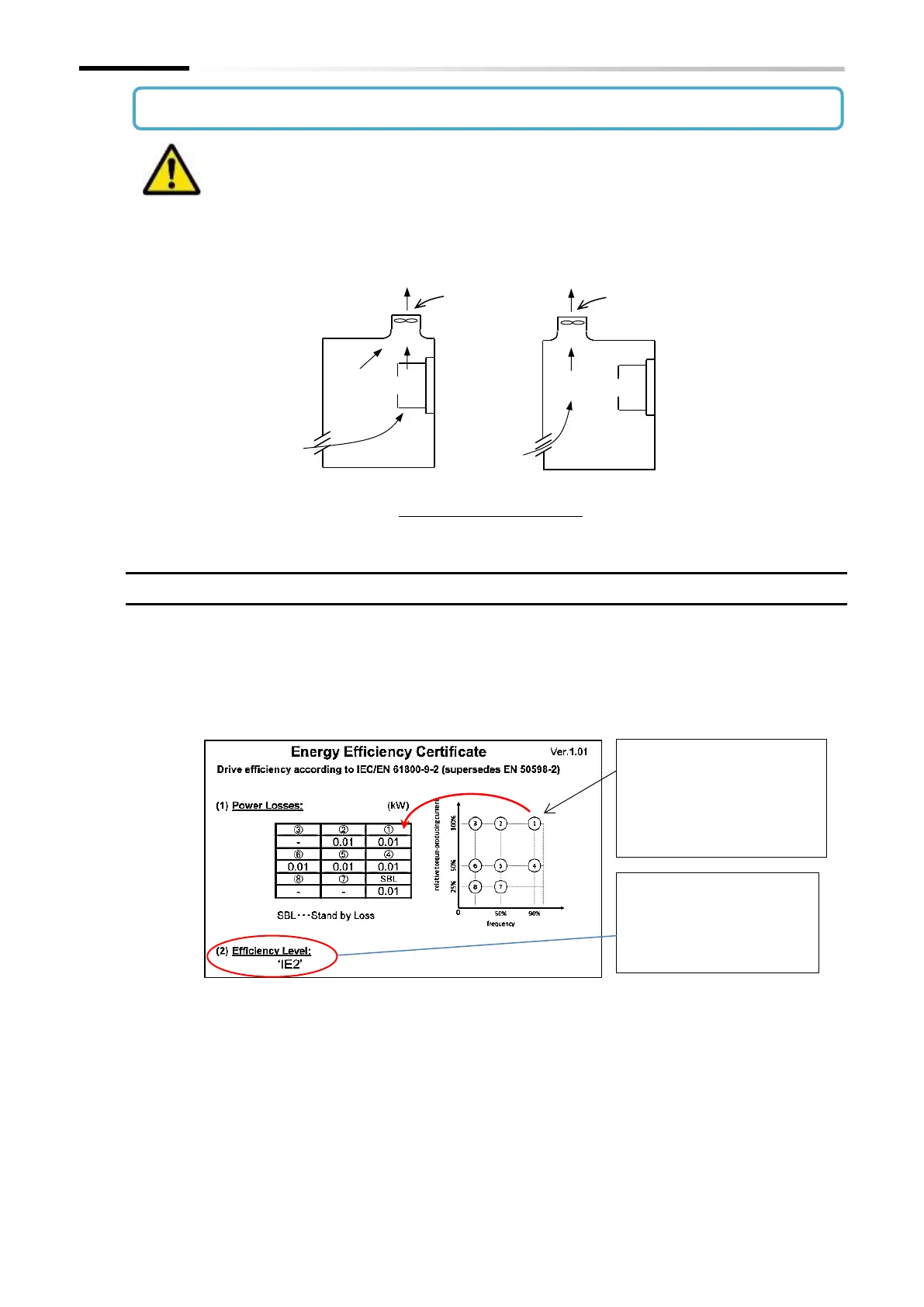
(4) The inverter losses at each point shown by the numbers on the Output Frequency vs. Load
Factor (ND Rating) graph at the right of the figure above are shown in the table on the left.
(5) Calculate the calorific value based on the inverter operation status and generated loss.
Position of ventilation fan
◆ Mounting in an enclosure
Indicates the efficiency level
specified in IEC60034-30
"Efficiency classes for single-
speed three-phase induction
① shows the inverter power
loss at 90% of the motor rated
frequency and load 100% (ND
rating).
(In the example shown at left, ①
is 0.01 kW)

 Loading...


