D2 Series Servo Drive User Manual Drive Configuration
HIWIN MIKROSYSTEM CORP. 5-41
Input function
Switch to secondary vpg Operation mode Pos Vel Trq Std
Symbol JSEL Default input None Circuit Refer to 4.5.1
Switch between velocity loop gains.
Instructions:
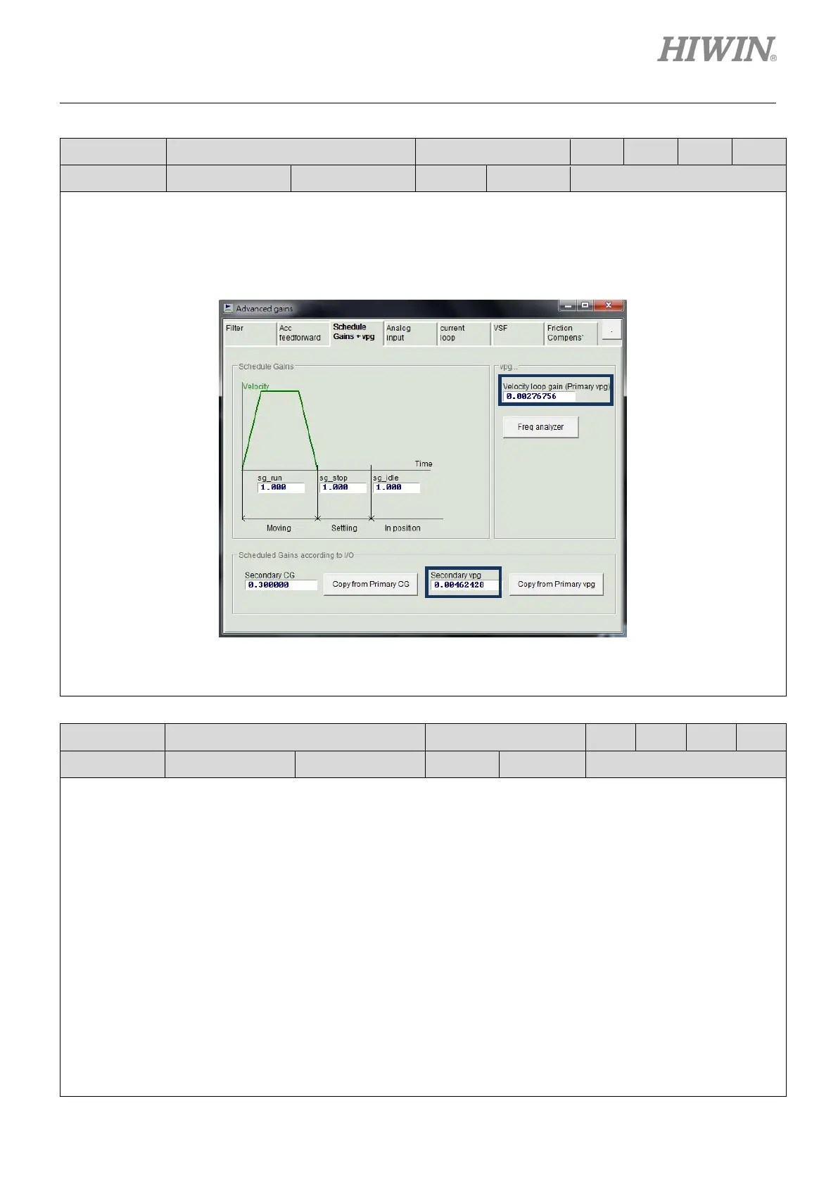
Different velocity loop gains can be set in the “Schedule Gains + vpg” tab of “Advanced gains” window
shown in the following figure.
When the input state of “Switch to secondary vpg” is True (the light is on), “Secondary vpg” is used. When
False (the light is off), “Primary vpg” is used.
Input function
Zero Speed Clamp Operation mode Pos Vel Trq Std
Symbol ZSC Default input I1 Circuit Refer to 4.5.1
This input function is only applicable to the velocity mode and is level triggered. When the input state of “
Speed Clamp” is True,
if the motor speed corresponding to the analog input voltage command is equal to or less
than the brake start speed, the operation mode will be switched to the stand-alo
ne mode automatically, and the
motor will be locked at the current position. Until the motor speed corresponding to the analog input voltage
command is larger than the brake start speed, the operation mode will be switched to the velocity mode
automatically to let the motor continue moving, as shown in the following figure.

 Loading...
