LCD Operation D2 Series Servo Drive User Manual
7-20 HIWIN MIKROSYSTEM CORP.
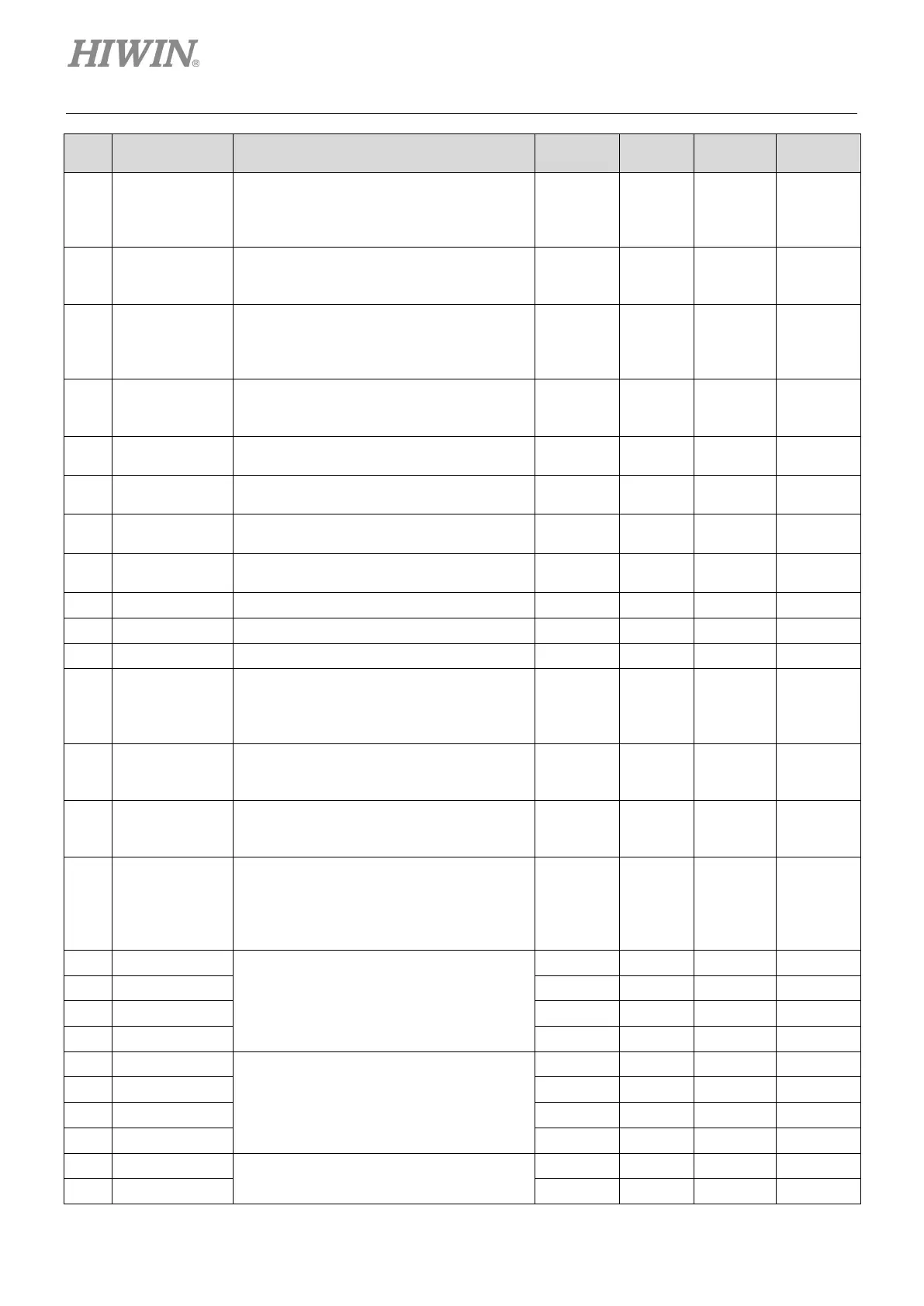
Parameter Definition Unit Default Max. Min.
083
X_cmd_ext_v_s
c
Velocity command scale; the speed
corresponds to 1 V, or the maximum
speed corresponds to “Full PWM”
(recommended value: rated speed/10)
rpm/V or
rpm/Full
PWM
60 3.4X10
38
-3.4X10
38
084
X_cmd_ext_v_d
z
Dead band of velocity command. The
speed command is 0 when the input
voltage is less than the set value
Volt 0 10 0
085
X_cmd_ext_i_s
c
Current command scale; the output
current corresponds to 1 V, or the
maximum current corresponds to “Full
A
amp
/V or
A
amp
/ Full
PWM
peak
current/1
3.4X10
38
-3.4X10
38
086
X_cmd_ext_i_d
z
Dead band of current command. The
current command is 0 when the input
voltage is less than the set value
Volt 0 10 0
088
Warning threshold for the position error
count
2
31
- 1 1
089
Warning threshold for the velocity error
count/s 10
8
3.4X10
38
1
092
X_ vel_stop Brake start speed
count/s
3.4X10
38
1
093
Delay time for starting brake
66.67 μs 500 ms 2
31
- 1 1
31
31
129
#
X_pulse_mode
0: Quadrature (AqB)
1: Pulse/Direction
2: Pulse up/Pulse down (CW/CCW)
-
bit
0: for 13
2 0
130
#
X_pulse_dir
0: Not inverse
- 0 1 0
131
#
X_fall_rise
Trigger method of pulse command
0: Falling edge
- 0 1 0
132
#
X_cmd_pwm_m
ode
Input command format for the velocity and
torque modes
0: Analog
1: PWM 50%
- 0 2 0
CN2 BRK output signal setting
15
out_config[1]
- 0 2
15
- 1 0
15
15
O1 output signal setting
15
15
15
15
O2 output signal setting
15
15
 Loading...

