3 Programming the Analyzer
STATus Subsystem
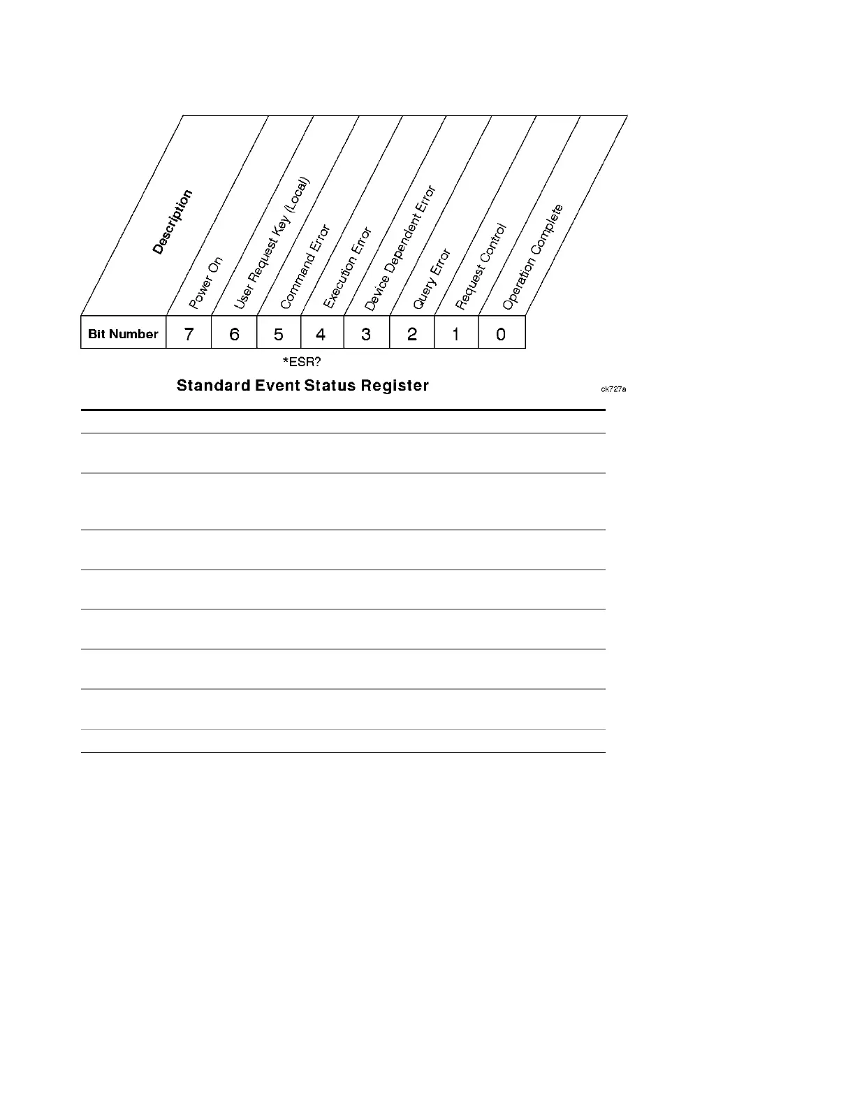
Bit Description
0 A 1 in this bit position indicates that all pending operations were completed following
execution of the *OPC command.
1 This bit is for GPIB handshaking to request control. Currently it is set to 0 because
there are no implementations where the spectrum analyzer controls another
instrument.
2 A 1 in this bit position indicates that a query error has occurred. Query errors have
SCPI error numbers from –499 to –400.
3 A 1 in this bit position indicates that a device dependent error has occurred. Device
dependent errors have SCPI error numbers from –399 to –300 and 1 to 32767.
4 A 1 in this bit position indicates that an execution error has occurred. Execution errors
have SCPI error numbers from –299 to –200.
5 A 1 in this bit position indicates that a command error has occurred. Command errors
have SCPI error numbers from –199 to –100.
6 A 1 in this bit position indicates that the LOCAL key has been pressed. This is true even
if the instrument is in local lockout mode.
7 A 1 in this bit position indicates that the instrument has been turned off and then on.
The standard event status register is used to determine the specific event that set bit 5 in the status byte
register. To query the standard event status register, send the command *ESR?. The response will be the
decimal sum of the bits which are enabled (set to 1). For example, if bit number 7 and bit number 3 are
enabled, the decimal sum of the 2 bits is 128 plus 8. So the decimal value 136 is returned.
In addition to the standard event status register, the standard event status group also contains a standard
event status enable register. This register lets you choose which bits in the standard event status register
will set the summary bit (bit 5 of the status byte register) to 1. Send the *ESE <integer> command where
<integer> is the sum of the decimal values of the bits you want to enable. For example, to enable bit 7 and
bit 6 so that whenever either of those bits is set to 1, the standard event status summary bit of the status
EMI Receiver Mode Reference 109
 Loading...


