10 Monitor Spectrum Measurement
Meas Setup
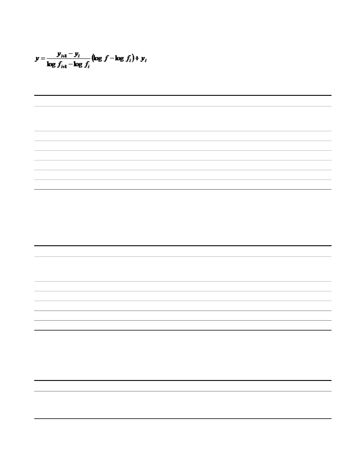
The Interpolation modes determine how limit values are computed between points in the limit table. The
appearance of a limit trace is also affected by the amplitude scale, which may be linear or logarithmic.
Key Path
Meas Setup, Limits, Properties, Interpolation
Remote Command
:CALCulate:LLINe[1]|2|...|6:CONTrol:INTerpolate:TYPE LOGarithmic |
LINear
:CALCulate:LLINe[1]|2|...|6:CONTrol:INTerpolate:TYPE?
Example CALC:LLIN4:CONT:INT:TYPE LIN Sets limit line 4 frequency interpolation to linear.
Dependencies This key is grayed out if Time is the selected X Axis Units.
Preset Linear, not affected by Mode Preset, preset by Restore Mode Defaults.
State Saved Saved in instrument state
Range Log|Lin
Initial S/W Revision A.13.00
Amplitude Interpolation
Sets the interpolation to linear or logarithmic for the specified limiting points set, allowing you to determine
how limit trace values are computed between points in a limit table. See "Frequency Interpolation" on page
792 for the equations used to calculate limit values between points.
Key Path
Meas Setup, Limits, Properties, Interpolation
Remote Command
:CALCulate:LLINe[1]|2|...|6:AMPLitude:INTerpolate:TYPE LOGarithmic |
LINear
:CALCulate:LLINe[1]|2|...|6:AMPLitude:INTerpolate:TYPE?
Example CALC:LLIN:AMPL:INT:TYPE LIN Sets limit line 1 amplitude interpolation to linear.
Preset Linear, not affected by Mode Preset, preset by Restore Mode Defaults.
State Saved Saved in instrument state
Range Log|Lin
Initial S/W Revision A.13.00
Fixed/ Relative
Accesses a menu that lets you specify that the selected limit is relative to either the Center Frequency or
the Reference level.
Key Path
Meas Setup, Limits, Properties
Readback [Fixed] – if both Relative to CF and RL set to OFF.
[Rel to RL] – if only RL set to ON.
[Rel to CF] – if only CF set to ON.
EMI Receiver Mode Reference 793