Function library
7-54
L
EDSVS9332P-D21 EN 3.0
7.5.8.6 Homing mode 4 and 5
Purpose
•
Simple homing in all positioning modes (C1210 = 0, 1, 2).
•
The homing switch (POS-REF-MARK) will not be overridden. Positions to the right of the
homing switch cannot occur due to the mechanical design.
•
The homing switch must be in direction of the movement.
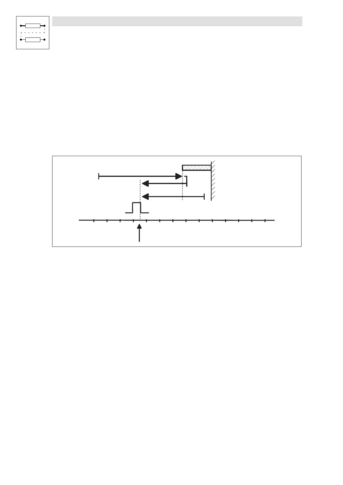
Move to homing switch, reverse and move to reference point
Mode 4: Traversing direction to the positive end of the travel range limit switch
Set C1213 = 4.
9300POS034
H o m e p o s i t i o n
Z e r o i m p u l s e / Z e r o p o s i t i o n
R e f e r e n c e s w i t c h
( P O S - R E F - M A R K )
Fig. 7-24 Move to POS-REF-MARK, reverse and move to reference point
Function procedure
•
Move towards travel range limit switch with homing speed C1242 up to homing switch (case
).
•
Reverse there and move to the reference point. The homing switch must be assigned during
theentirehomingprocess!
•
The reference point is at the first zero pulse / zero position of the position encoder after leaving
the homing switch.
•
If the drive is already positioned on the homing switch before homing it is reversed
immediately
(c ase ).
Mode 5: Traversing direction to negative end of travel range limit switch
Set C1213 = 5.
Function procedure
•
Like mode 4, but the drive traverses in negative direction of travel range limit switch.

 Loading...


