Function library
7-55
L
EDSVS9332P-D21 EN 3.0
7.5.8.7 Homing mode 6 and 7
Purpose
•
Homing in all positioning modes (C1210 = 0, 1, 2).
•
Use of touch probe if the index pulse does not appear at the same place in a reproducible
form due to the mechanical constellation. The index signal can also be mechanically shifted
after a motor exchange.
•
The homing switch (POS-REF-MARK) must be in direction of the movement.
Travel to TP signal via homing switch
Mode 6: Traversing direction to positive end of travel range limit switch
Set C1213 = 6.
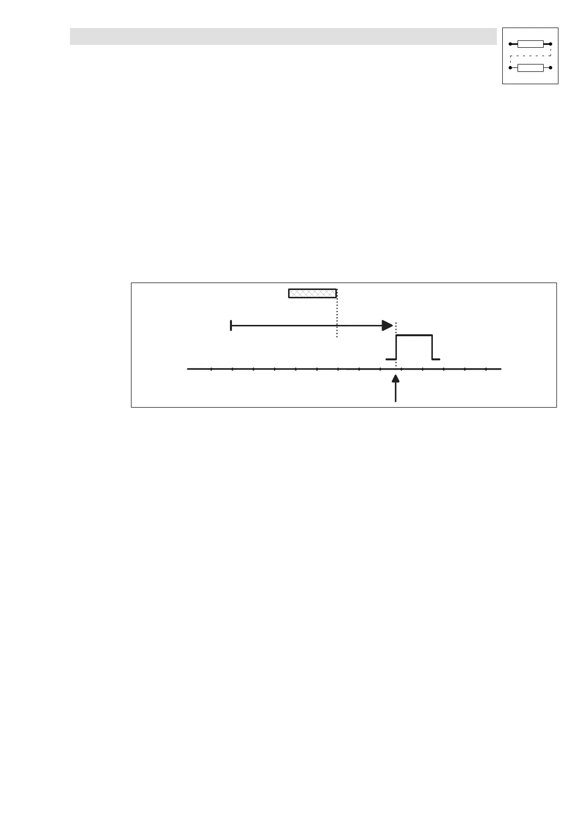
H o m e p o s i t i o n
T P s i g n a l
H o m i n g s w i t c h ( P O S - R E F - M A R K )
9300pos054
Fig. 7-25 Move to TP signal via POS-REF-MARK
The following settings are necessary:
•
Select terminal for TP initiator via C1214.
– C1214 = 1 ≙ Te r m i n a l X5 / E1 .
– C1214 = 2 ≙ Te r m i n a l X5 / E2 .
– C1214 = 3 ≙ Te r m i n a l X5 / E3 .
– C1214 = 4 ≙ Terminal X5/E4 (this setting is recommended by LENZE).
•
Select edge of the TP input via C1215.
– C1215 = 0 ≙ LOW-HIGH edge.
– C1215 = 1 ≙ HIGH-LOW edge.
Function procedure
•
Move to the home position with homing speed (C1242) towards positive end of travel range
limit switch overriding the homing switch.
•
After leaving the homing switch the reference point is determined by the TP signal. TP signals
that occurred before are ignored.
•
The drive may be positioned on the homing switch before homing.
Modus 7: Traversing direction to negative end of travel range limit switch
Set C1213 = 7.
Function procedure
•
As ”Traversing direction to positive end of travel range limit switch”, but the drive moves
towards the negative end of travel range limit switch.

 Loading...


