Function library
7-262
L
EDSVS9332P-D21 EN 3.0
7.5.76.1 Switching points
•
The switching points can be set in two ways:
– Mode 1: Start and end point
– Mode 2: Centre point with switching range
•
The switching points are entered via the variable table VTPOS.
– Direct input of the switch-on and switch-off points or centre point and range in VTPOS.
•
If the value at SPx-L-IN is within the range of the switching points set, SPx-STATx switches
HIGH
•
In factory setting, SPx-L-IN is connected to the actual position value (POS-ACTPOS) of the FB
POS.
– Therefore, the switching points refer to the distance traversed by the motor.
Assignment of the switch-on and switch-off points for SP1 (see also Fig. 7-211):
Code Subcode Switching point Output FB
C1641
1 IN1-1
SP1-STAT1
2 IN1-2
... ... ... ...
C1641
15 IN8-1
SP1-STAT8
16 IN8-2
Assignment of the switch-on and switch-off points for SP2 (see also Fig. 7-212):
Code Subcode Switching point Output FB
C1651
1 IN1-1
SP2-STAT1
2 IN1-2
... ... ... ...
C1651
15 IN8-1
SP2-STAT8
16 IN8-2
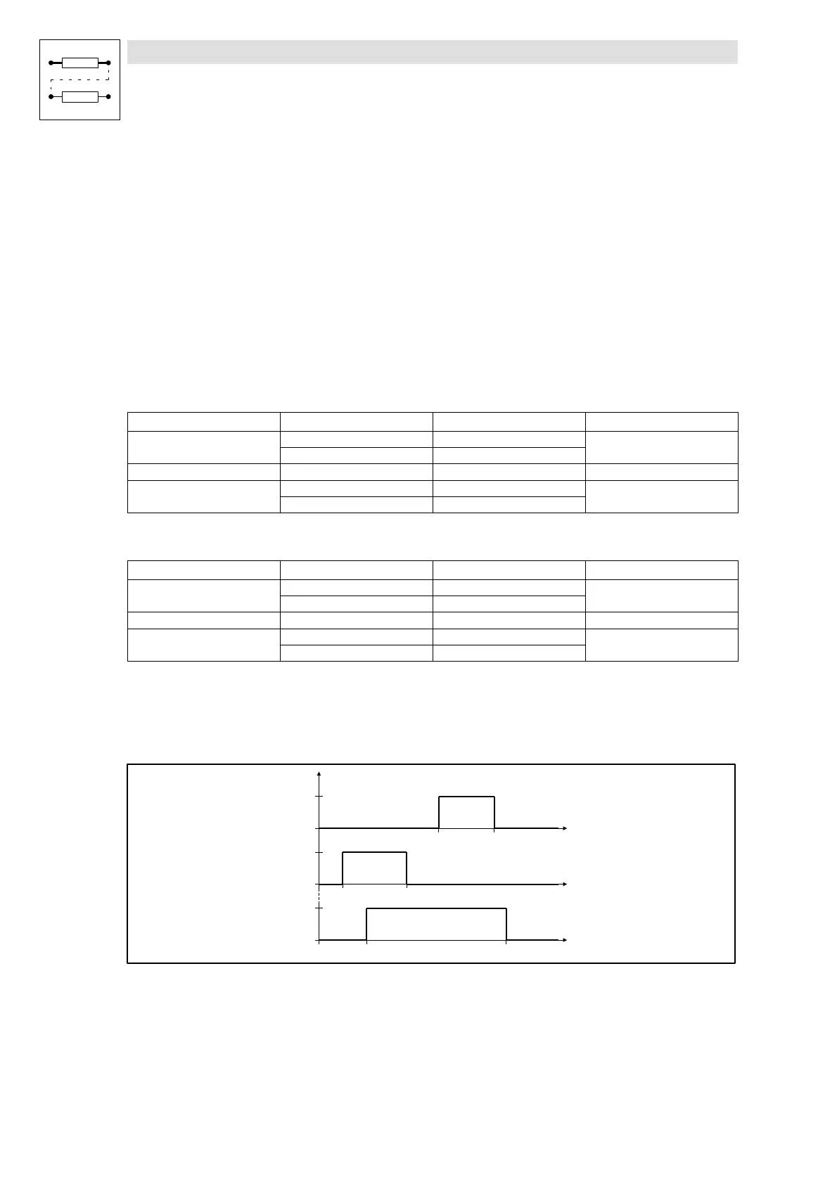
Mode 1: Start and end point
C1645 = set 0 (SP1)
C1655 = set 0 (SP2)
SPx-L-IN
SPx-L-IN
SPx-L-IN
Px-STAT1
Px-STAT2
Px-STAT8
IN1-1 IN1-2
IN2-1 IN2-2
IN8-1 IN8-2
HIGH
LOW
HIGH
LOW
HIGH
LOW
Fig. 7-213 Switch-on and switch-off points for SPx-STAT1, SPx-STAT2 and SPx-STAT8

 Loading...


