Function library
7-180
L
EDSVS9332P-D21 EN 3.0
7.5.45.1 Profile generator
t
DFRFG-IN
C0752
C0751 C0751
C0755
DFRFG-SYNC
t
DFRFG-OUT
Fig. 7-136 Synchronisation on DFRFG
The profile generator generates ramps which lead the setpoint phase to its target position.
•
Set acceleration and deceleration via C0751.
•
Set max. speed via C0752.
•
When distance and speed reach their setpoints, the output switches DFRFG1-SYNC = HIGH.
AtthesametimetheFBswitchestheprofilegeneratorto”inactive”.
•
Set the switching point via C0755.
Stop!
Do not operate the drive with this function at the torque limitation M
max
,I
max
.
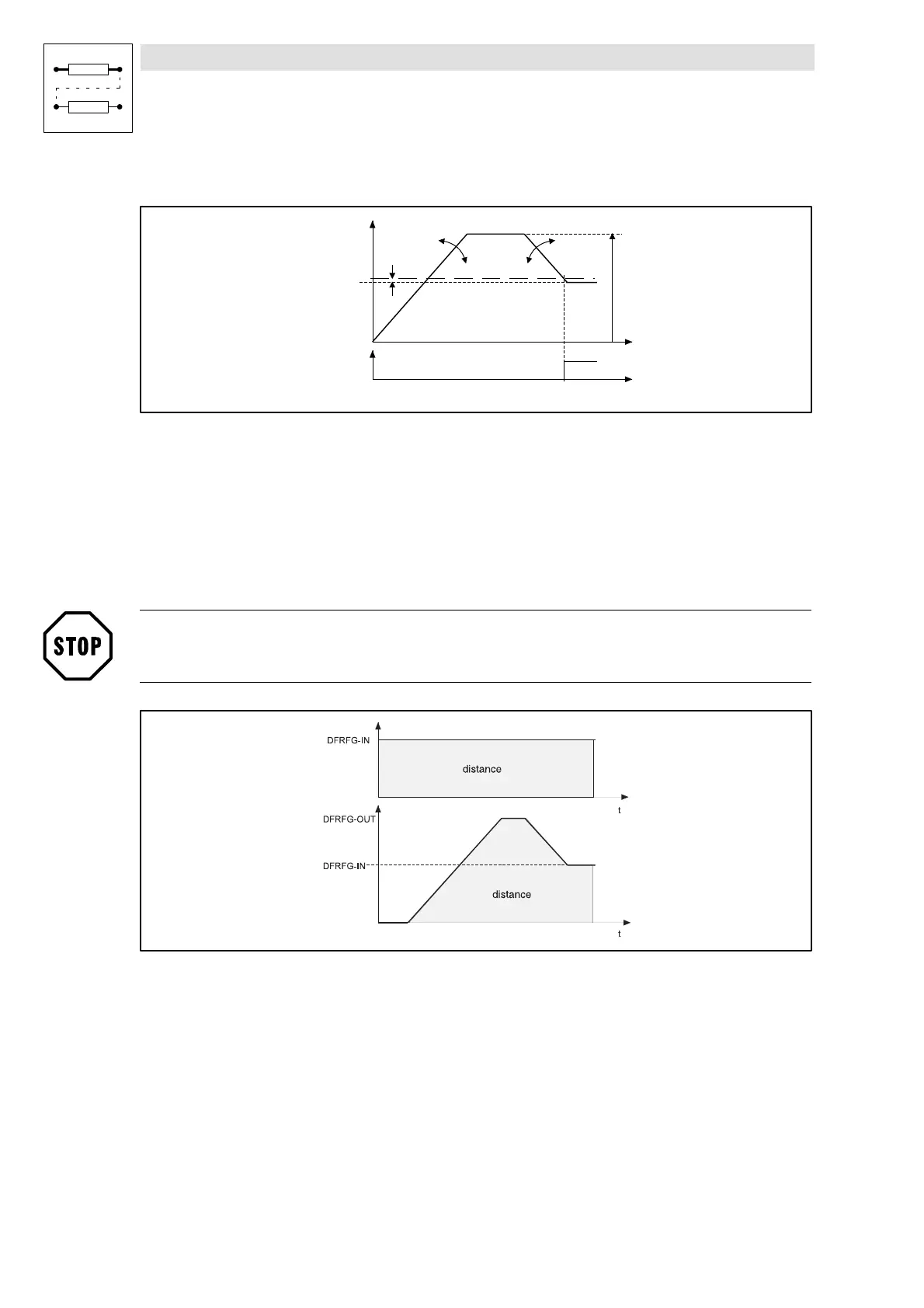
Fig. 7-137 Speed-time diagram DFRFG
The number of increments at DFRFG-IN (master drive) defines the target position. The target can be
displayed as a path. The speed-time diagram shows the distance covered (angle) as the area below
the speed profile. When synchronisation is reached, master and slave have covered the same
distance (phase).

 Loading...


