Installation
4-2
L
EDSVS9332P-B EN 3.0
4.1.2 Standard assembly with fixing rails or fixing brackets
K35.0001c
A B C
X
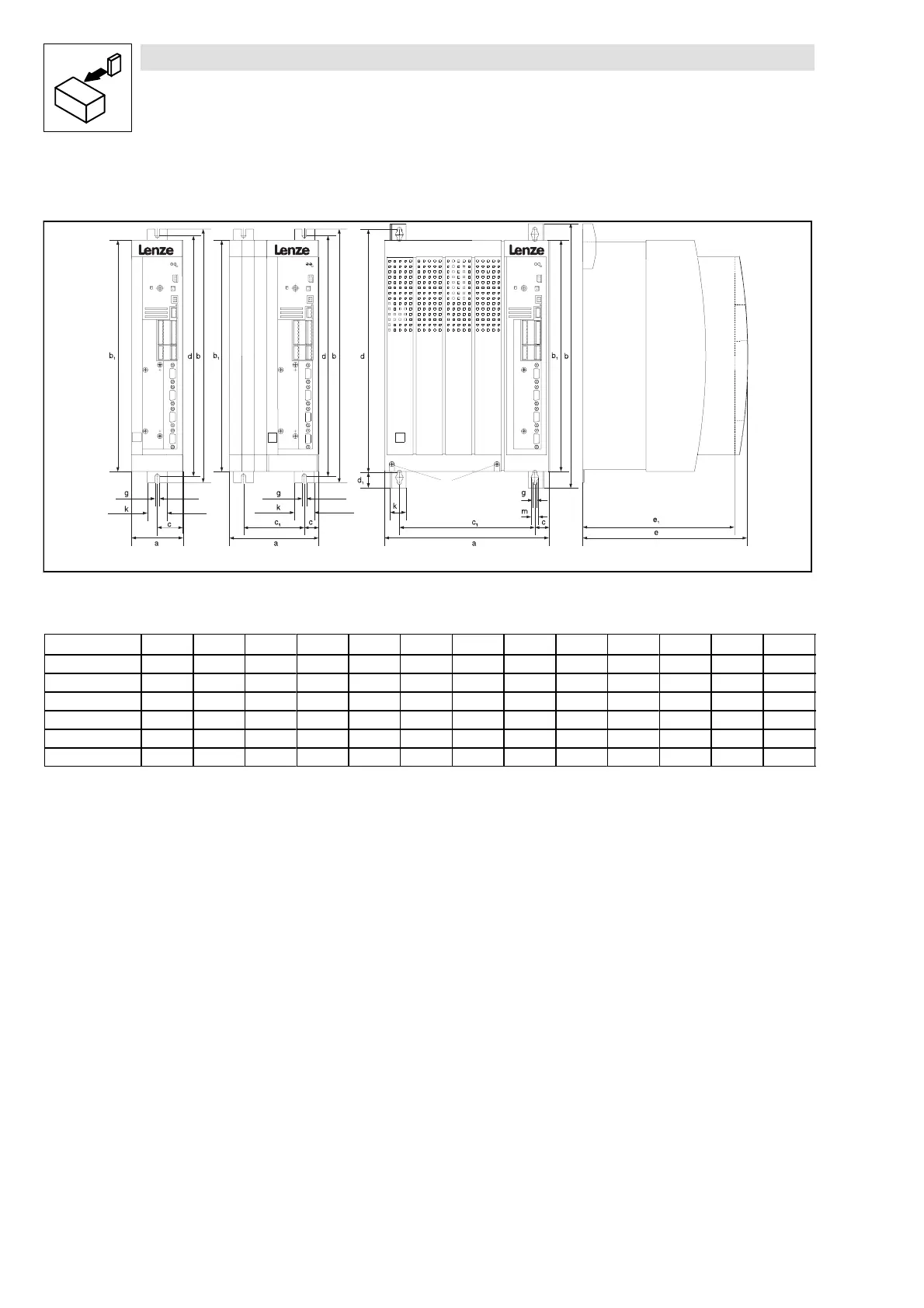
Fig. 4-1 Dimensions for assembly with fixing rails/fixing brackets
Type Fig. a b b1 c c1 d d1 e* e1 g k m
9321, 9322 A 78 384 350 39 - 365 - 250 230 6.5 30 -
9323, 9324 A 97 384 350 48.5 - 365 - 250 230 6.5 30 -
9325, 9326 B 135 384 350 21.5 92 365 - 250 230 6.5 30 -
9327, 9328, 9329 C 250 402 350 22 206 370 24 250 230 6.5 24 11
9330 C 340 672 591 28.5 283 624 38 285 265 11 28 18
9331, 9332 C 450 748.5 680 28.5 393 702 38 285 265 11 28 18
*
When using an attachable fieldbus module:
Observe the free space required for the connection cables
All dimensions in mm
Controllers 9321 to 9326
•
Assembly preparation:
– Take out fixing rail(s) (accessory kit in the box) and mount them on the controller housing
Controllers 9327 to 9332
•
Remove cover:
– Loosen screws (X)
– Swing cover upwards, and detach.
– Take accessory kit out of the interior of the controller
•
Assembly preparation:
– Take out fixing bracket and screws (accessory kit) and mount them on the controller
housing

 Loading...


