Function library
7-272
L
EDSVS9332P-D21 EN 3.0
Interpolation cycle time (INTPOL. CYCLE)
The FB interpolates the input signals (C1124, C1125, C1126) between the sync telegrams or sync
signals and transmits them to the corresponding output. This ensures an optimum signal course with
regard to the internal processing cycle (e. g. minimising signal jumps in the output variable when
operating with high sync cycles).
The interpolation is restarted with every sync signal (LOW-HIGH edge).
Code Value Function
C1121/2 1 ... 13 ms Definition of the interpolation cycle / steps
•
C1120 = 1
– C1121/2 has no effect.
– The interpolation cycles are derived from the sync cycle (C1121/1).
•
C1120 = 2
– The interpola tion cycle can be selected irrespective of the sync cycle.
– The parameter setting of C1121/2 must be selected according to the cycle of the process value
input.
T
S Y N C
C A N N E L 1
S Y N C
-
S I G N A
[ 1 0 V ; 1 m s ]
G N D 1
C A N N E L 2
S Y N C 1 - I N 3
[ x , x % ; 1 m s ]
C A N N E L
3
S Y N C 1 - O U T 3
[ x , x % ; 1 m s ]
G N D 2
G N D 3
T
I N T P O L
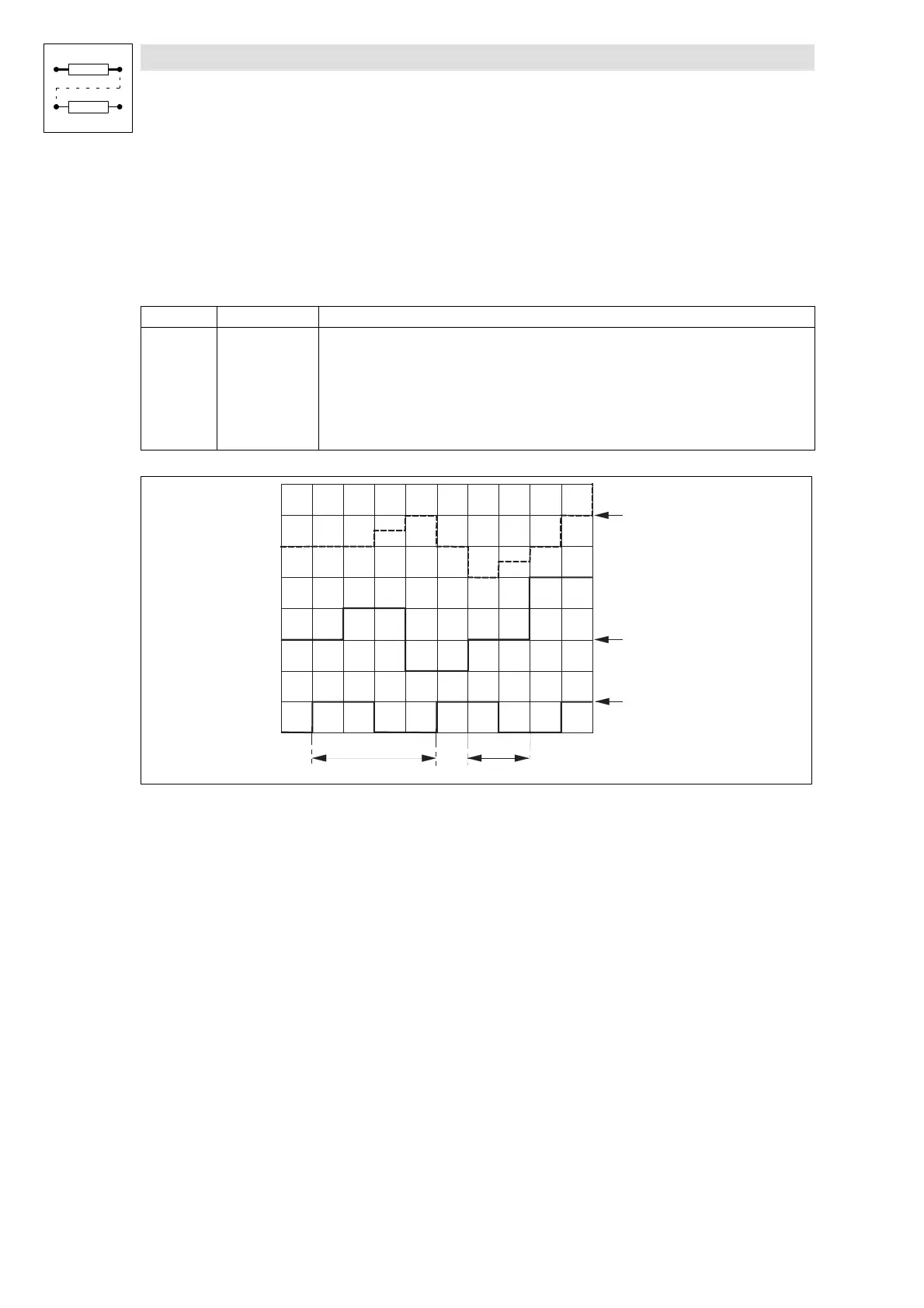
Fig. 7-222 Interpolation example
See Fig. 7-222:
An analog value at SYNC1-IN3 is output as an interpolated value at SYNC1-OUT3.
•
Sync cycle (C1121/1) = 4 ms
•
Interpol. cycle (C1121/2) = process cycle = 2 ms
•
Phase displacement (C1123/1) = 0 ms

 Loading...


