Appendix A: Installation and Setup
MP65492–1 167 Linx 4900 Operating Manual
This typically requires trial and error; first select an encoder/gear
combination, and then multiply it by whole numbers to get the actual pitch.
This is then compared to the required pitch.
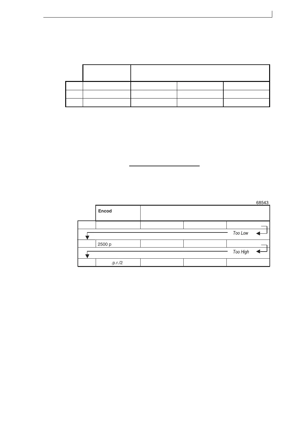
Figure A-12 Selecting Encoder Pitch Combinations
For each encoder pitch that you try, the starting point for the pitch factors
can be:
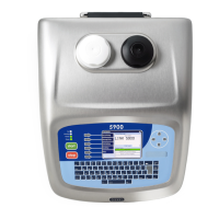
Using the example from Step 1, the required raster pitch is 0.373 mm. A
standard Linx encoder and wheel is used to try to achieve this.
Figure A-13 Example Encoder Pitch Combinations
The actual raster pitch from Try 3 is close enough to the required raster
pitch to be used, particularly as the required raster pitch is the maximum,
therefore, a 5000 p.p.r. encoder and a 200 mm wheel is specified, and the
pitch factor is 9.
It can be seen that the higher the encoder pulses per revolution, the closer
the actual pitch approaches the required pitch. This also gives the
possibility of accommodating changes in the required pitch, however, the
cost of the encoder will be higher and there may be limitations in terms of
speed.
Pitch Factor (rounded to the nearest whole number) =
Required Pitch (mm)
Encoder Pitch (mm)
6512
Encoder/Gearing Encoder Pitch x Pitch Factor = Actual Raster
Pitch
Try 1
Try 2
Try 3
$&#"!
Encoder/Gearing
Encoder Pitch x Pitch Factor = Actual Raster
Pitch
Try 1
2500 p.p.r./200 mm 0.080 mm 4 0.32 mm
Too Low
Try 2
2500 p.p.r./200 mm 0.080 mm 5 0.40 mm
Too High
Try 3
5000 p.p.r./200 mm 0.040 mm 9 0.36 mm
4900 Op Manual.book Page 167 Tuesday, September 9, 2003 12:32 PM