215575 169 Revision B
Figure 4.131: Header Down Switch
3. On the ground speed lever (GSL), press HEADER DOWN
button (A). The sensor values on the HEADER CALIBRATION
page will change as the header falls.
NOTE:
The header needs to be fully lowered and then fully raised.
The sensor voltage range should be between 0.7 and 4.3 V.
If the values do not fall within that range, the height
sensors will need to be adjusted. For instructions, refer to
4.4.2 Adjusting Header Height Sensor Voltage Range – Left
Side, page 114 or 4.4.3 Adjusting Header Height Sensor
Voltage Range – Right Side, page 114.
Figure 4.132: Header Calibration
4. When the sensor values are stable, touch CALIBRATE
icon (A).
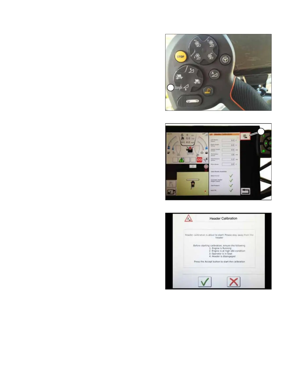
Figure 4.133: Header Calibration Warning
5. The hazard message for the HEADER CALIBRATION
procedure appears. Before touching the green check mark,
ensure that all the conditions listed on the page have been
met.
6. Touch the green check mark to start the CALIBRATION
WIZARD.
AUTO HEADER HEIGHT CONTROL