215575 248 Revision B
$
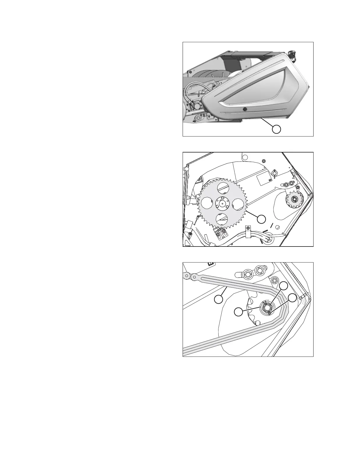
Figure 5.63: Left Endshield
3. Open left endshield (A). For instructions, refer to 3.3.1
Opening Left Endshield, page 25.
$
Figure 5.64: Driven Sprocket
4. If the header is not attached to the combine, place a pry
bar or equivalent through a hole in driven sprocket (A) and
against the frame to stop the driveshaft from rotating.
$
%
&
'
Figure 5.65: Drive Sprocket
5. Remove cotter pin (B).
6. Remove M20 castle nut (C) and washer (D) from the
driveshaft.
7. Remove chain (A). For instructions, refer to Removing
Auger Drive Chain, page 242.
MAINTENANCE AND SERVICING