215575 247 Revision B
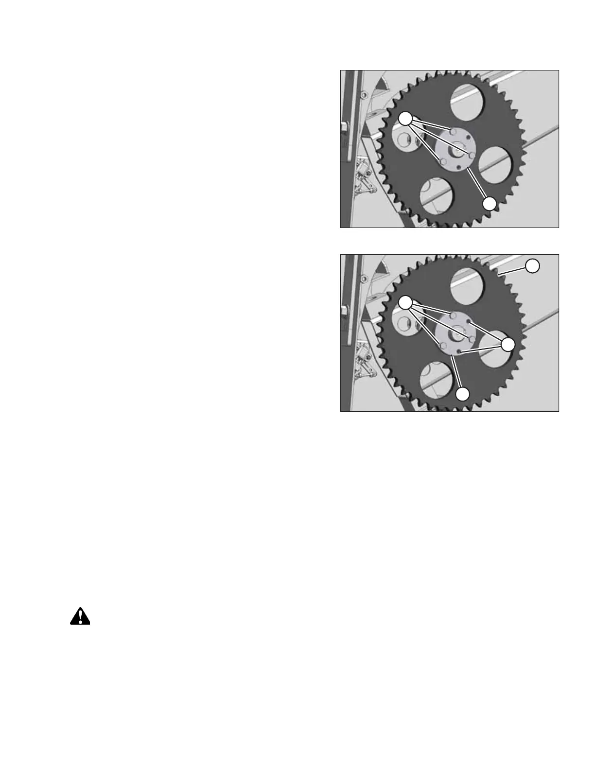
Figure 5.61: Driven Sprocket
8. Torque three M10 hex bolts (A) in equal increments to
44 Nm (32 lbf·ft) while maintaining the alignment between
the sprockets.
9. Tap bushing (B) with a hammer and torque the bolts again.
Repeat this step three times or until the bolts no longer
turn at 44 Nm (32 lbf·ft).
Figure 5.62: Driven Sprocket
10. Check the alignment of the sprockets again. If the
alignment is off by more than 1 mm (3/64 in.), follow these
steps:
a. Measure and record the position of tapered
bushing (D) relative to the driveshaft.
b. Remove three M10 hex bolts (A) from tapered
bushing (D).
c. Reinstall two M10 hex bolts (A) into threaded holes (B)
in tapered bushing (D).
d. Alternately turn M10 hex bolts (A) into tapered
bushing (D) in half-turn increments until the tapered
bushing and sprocket (C) can be moved.
e. Reposition tapered bushing (D) to account for the
misalignment.
f. Repeat Step 5, page 246 to Step 10, page 247.
g. Check the sprocket’s alignment.
h. Repeat Step 10, page 247 until the sprockets are in
alignment.
11. Install and tension the chain. For instructions, refer to Installing Auger Drive Chain, page 243.
12. Close the left endshield. For instructions, refer to 3.3.2 Closing Left Endshield, page 26.
Removing Drive Sprocket
If the header is not attached to the combine, you will have to lock the rotation of the driven sprocket to remove the drive
sprocket.
WARNING
To avoid bodily injury or death from unexpected startup of machine, always stop the engine and remove the key from
the ignition before leaving the operator’s seat for any reason.
1. Lower the header to the ground.
2. Shut down the combine and remove the key from the ignition.
MAINTENANCE AND SERVICING