NOTICE
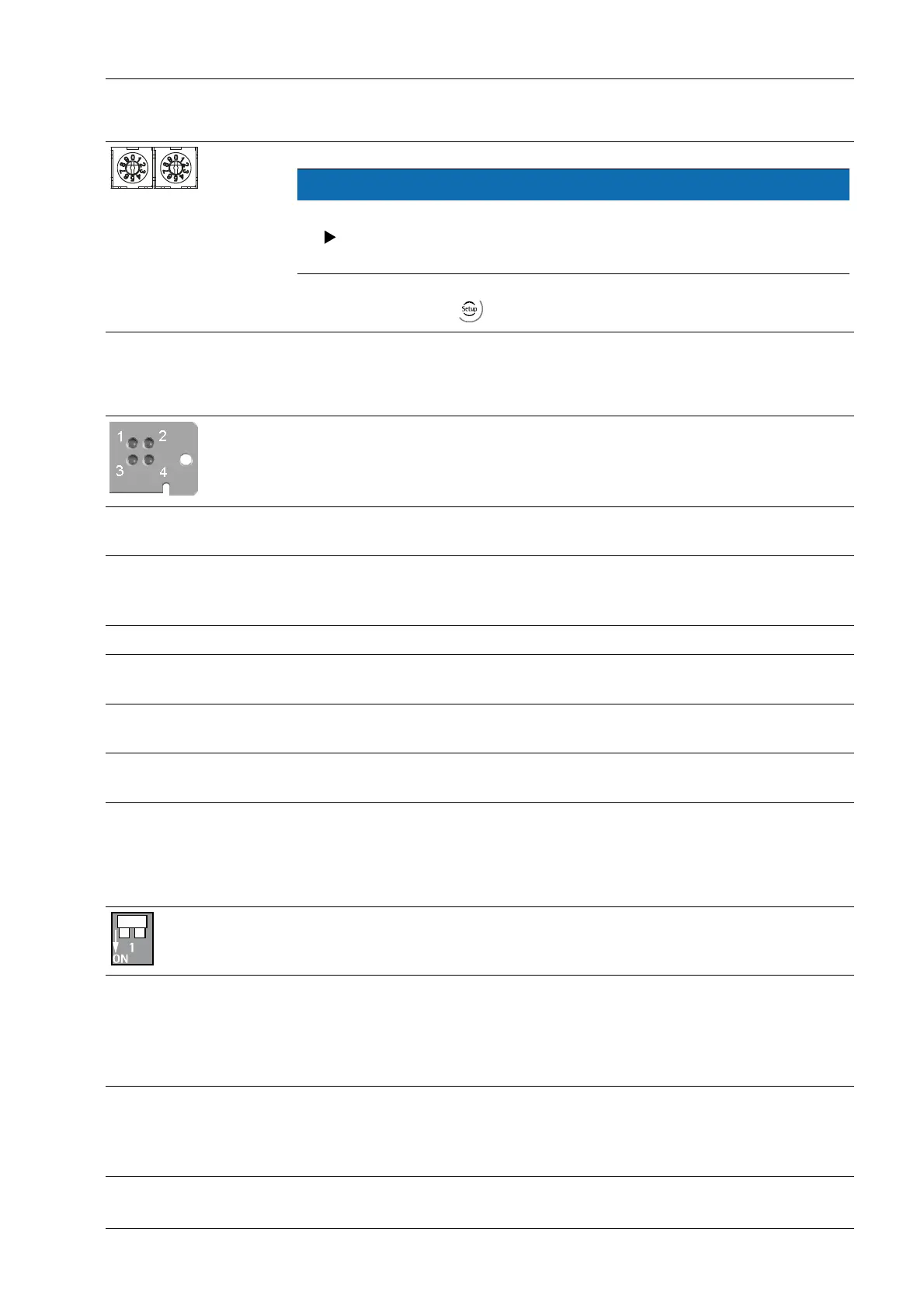
The ④④ rotary switch settings will not be used.
Ensure that the three rotary switches for node address 1…99 are set to po-
sition "0."
Settings are defined via
- [Fieldbus parameter][Profibus-DP].
4.6.13.2 LEDs in the module cover
The module cover can be found at the rear of the device.
⑥⑥
LED 1
No function
LED 2 LED 3 LED 4
Off No diagnostics avai-
lable
Constant green Module is online, da-
ta transmission is
possible
Constant red Module is offline
Flashing 1 Hz red I/O length configu-
ration error
Flashing 2 Hz red Parameter, data
length error
Flashing 4 Hz red Communication,
ASIC error
4.6.13.3 Bus termination
The end nodes in a ProfiBus-DP network must be fitted with termination resistors, to
prevent reflections in the bus cable.
Bus termination switch ③ is located in the module cover and can
be accessed from outside.
Bus termination switch "ON" The bus termination is switched on.
If the module is the last or first in the network, this switch must be
set to "ON."
An "external" terminating resistor can also be used in the ProfiBus
connector, however.
Bus termination switch "OFF" The bus termination is switched off.
When using an external terminating resistor in the ProfiBus
connector, the switch on the module cover must be in position
"OFF."
4 Device installation X3 Process Indicator PR 5410
Minebea Intec EN-99