¾
3-2-4
¾
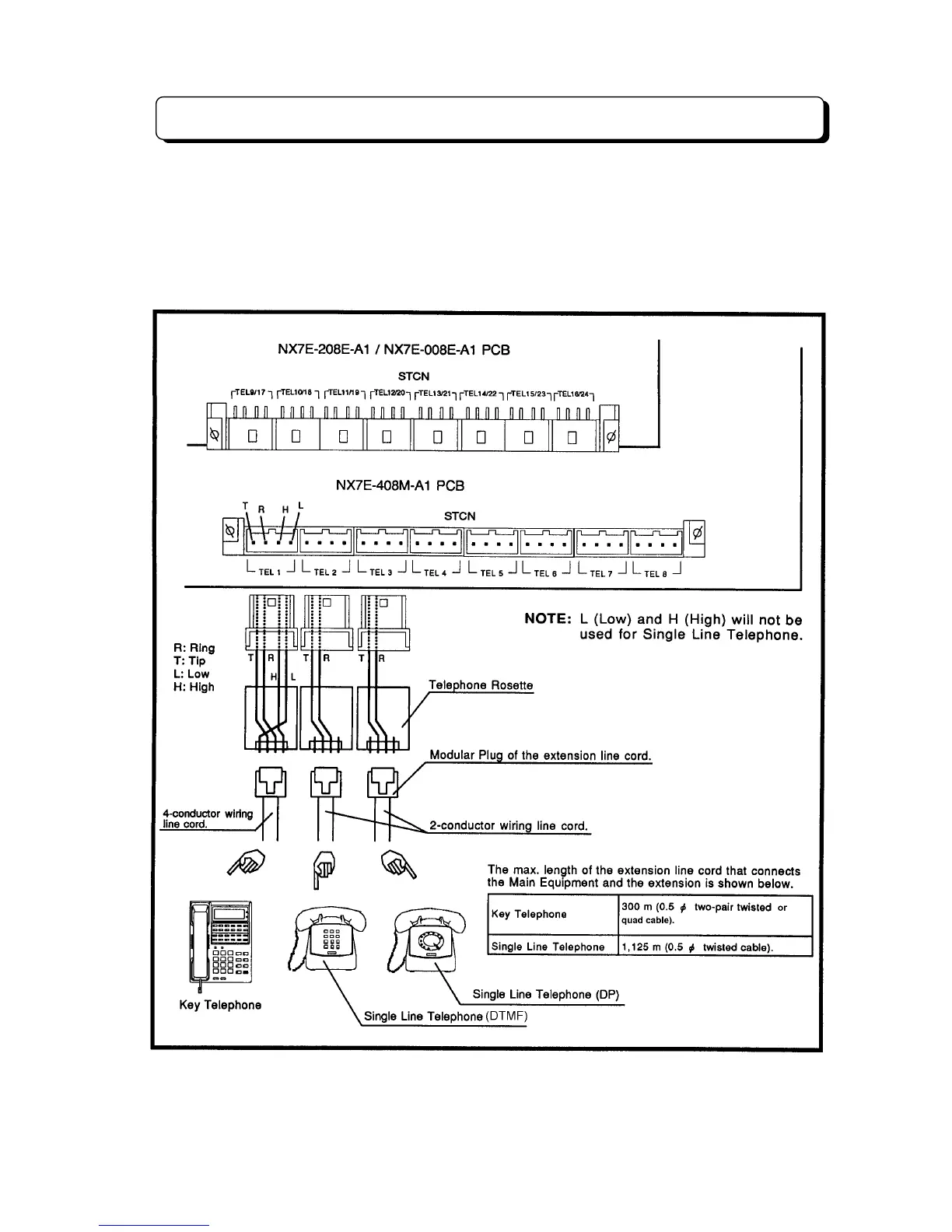
Extension Connection
The extension (Key Telephone and Single Line Telephone) shall be connected as illustration. Insert the
connector from the extension into the female connector on the units (NX7E-408M-A1, NX7E-208E-A1,
NX7E-008E-A1) labeled STCN. The basic system is equipped eight extension ports. If two expansion
units (NX7E-208E-A1 and/or NX7E-008E-A1) are installed, Up to twenty-four extensions can be
connected to the system. 4-conductor wiring is required for each extension when connecting Key
Telephone Set to the system. Use 2-conductor wiring for each extension when connecting Single Line
Telephone to the system. In other words, L (Low) and H (High) will not be used for Single Line
Telephone.