¾
3-2-5
¾
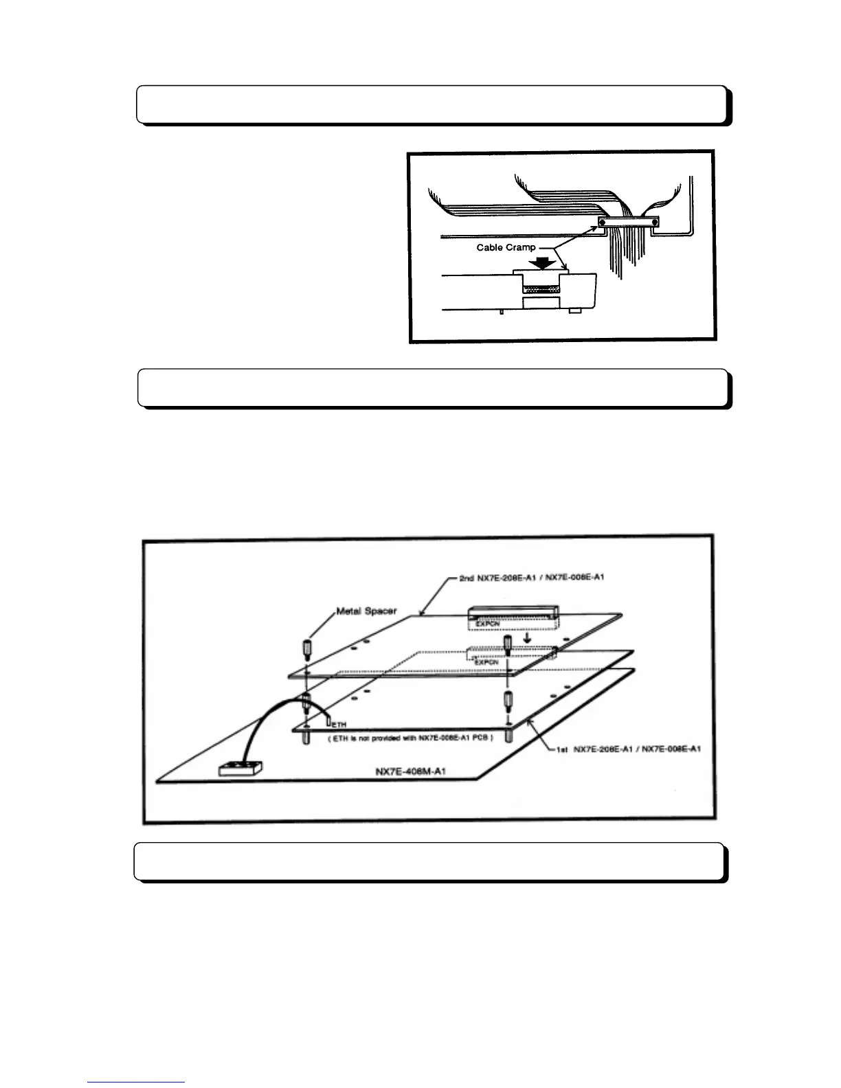
Cable Routing and Cramping
All cabling should exit from the right side of
the Main Equipment. Route and cramp the
cable for the Main Equipment as illustrated
on the right side.
Installing Expansion PCBs
The NX7E-208E-A1 PCB is CO/PBX and station interface card which provides two CO/PBX interface,
eight station interface. The NX7E-008E-A1 PCB is station interface card which provides eight station
interface. This two cards are required when expanding the your system.
Install NX7E-208E-A1 and/or NX7E-008E-A1 PCB into the Main Equipment as illustrated below. An earth
ground (ETH) connection is required whenever the NX7E-208E-A1 PCB is installed in the system.
Installing DLS Console
The TX-Z 824 system can accommodate up to 3 DLS Consoles used as DSS (Direct Station Selection)
console. Refer to “Installing DLS Console” in page 3-3-10.