¾
3-2-3
¾
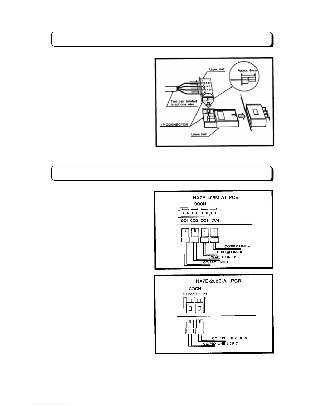
Connector Assembly
When connecting the wiring cables to the
connectors mounted on the units. Insert the
wires of each cable into the connector and
insert this connector to female connector on
the unit (see illustration).
Step 1:
As indicated in the illustration, insert
twisted or quad telephone wire (0.5 to
0.67 mm f) into the upper section of the
connector. Ensure that the lead wire ends do
not protrude beyond the rear surface of the
connector.
Step 2:
Install the upper section of connector
over the lower, and then compress the
assembled connector with pliers or the like.
Verify that the upper section of connector will
not come off the lower section.
Trunk Line Connection
The Trunk (CO/PBX) lines shall be
connected as illustration. Make connection
from Telecom provided connector to one of
the connector on the 408M-A1 or 208E-A1
units labeled COCN.
The TX-Z
824 system can be installed eight
Trunk lines maximum. The basic system is
equipped to accept four Trunk lines. If two
expansion units (NX7E-208E-A1 PCB) are
installed, four more Trunk lines may be
installed (see System Configuration Table).