¾
3-2-7
¾
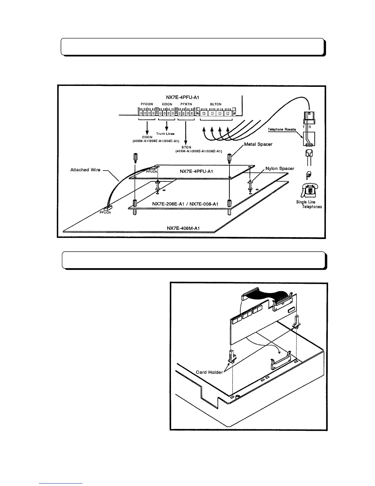
Installing 4PFU-A1 PCB
The NX7E-4PFU-A1 PCB provides 4 power failure cut through circuits to single line telephone. To install
PCB and connect the wires, refer to following a illustration.
Installing 8DHEXU-A1 PCB
The NX7E-8DHEXU-A1 PCB provides:
- Connections for two alarm sensors
- Connections for customer supplied
MOH and BGM
- Two Doorphone Box interfaces
- Two external paging outputs
- Two common-use relay contact
Step 1:
Insert the card holders
attached with the PCB into the
specified holes of the Main Equipment.
Step 2:
Insert a 8DHEXU-A1 PCB
along the card holders.
Step 3:
Connect the ribbon cable
attached with the PCB to the DHUCN
connector on the NX7E-408M-A1 PCB.