¾
3-2-8
¾
Installing the Doorphone Box
This section provides information on installing the Doorphone Boxes in a TX-Z
824 system.
Specifications:
150 m wire maximum of 0.5 f twisted telephone cable.
Step 1:
Mount the 8DHEXU-A1 PCB on the base unit of the Main Equipment (see "Installing 8DHEXU-
A1 PCB" on page 3-2-7).
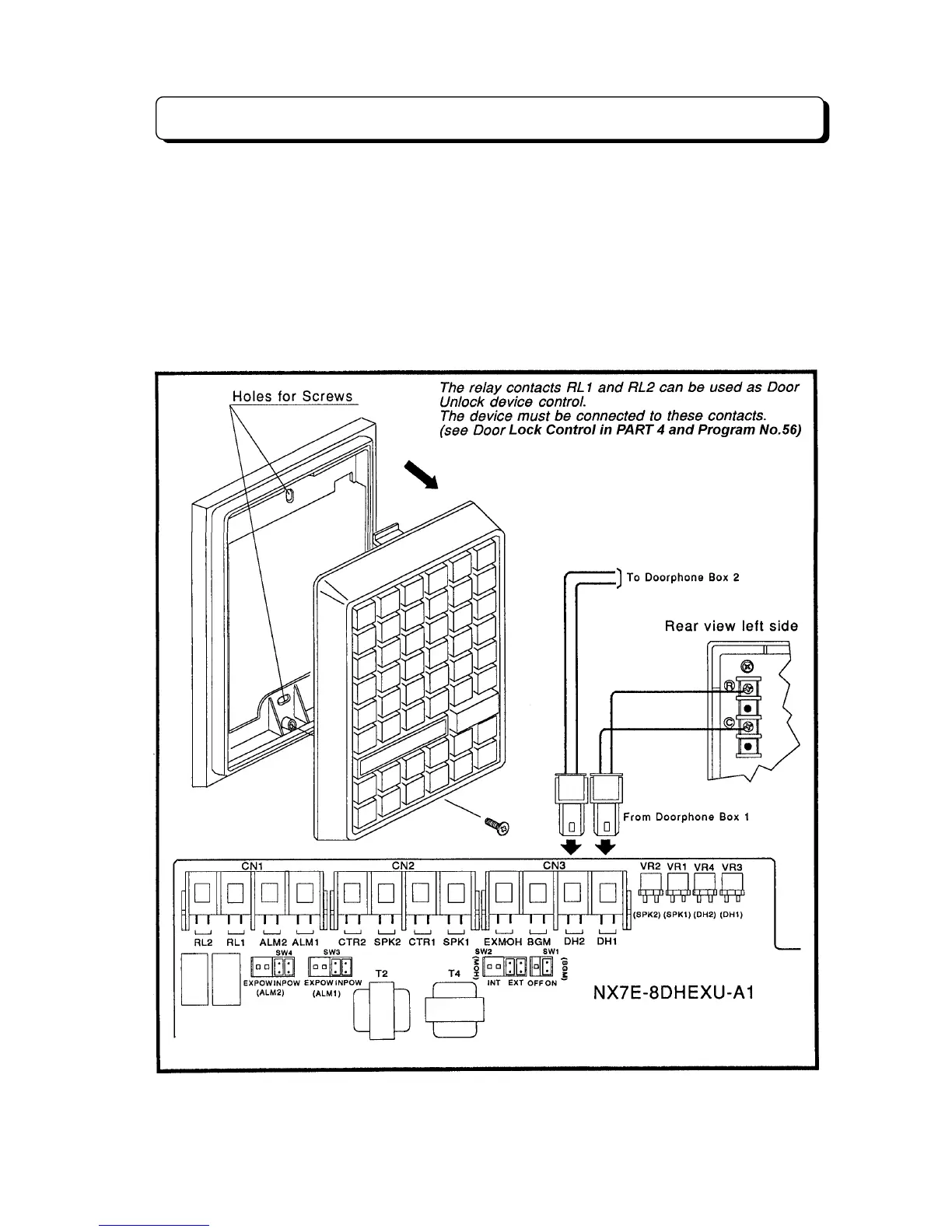
Step 2:
Connect wires to the terminal marked R and C on the back of the Doorphone Box, and connect
the other end to DH1 on the 8DHEXU-A1 PCB for Doorphone Box 1 or DH2 for Doorphone Box 2. (See
illustration below)
Step 3:
Adjust the audio level with VR3 on the 8DHEXU-A1 PCB in the Main Equipment for Doorphone
Box 1 or VR4 for Doorphone Box 2.