¾
3-2-6
¾
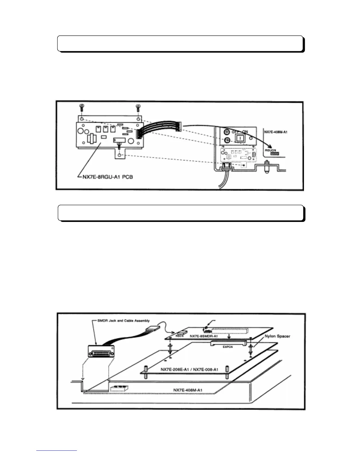
Installing the Ringer Unit
The ring generator source unit (NX7E-8RGU-A1 PCB) must be installed in the system when connected
the Single Line Telephone as system extension.
To install NX7E-8RGU-A1 PCB, mount the PCB on the right position of the Main Equipment, and connect
an attached cable to the connector mounted on the NX7E-408M-A1 PCB labeled RGUCN. (See the
following illustration.)
Installing the SMDR and Printer/PC
For use of the Station Message Detail Recording feature, NX7E-8SMDR-A1 PCB must be installed in the
system. To install the NX7E-8SMDR-A1 in the Main Equipment:
Step 1:
Insert the NX7E-8SMDR-A1 PCB into the connector labeled EXPCN on the units (NX7E-408M-
A1, NX7E-208E-A1 or NX7E-008E-A1).
Step 2:
Mount the SMDR Jack and Cable Assembly on the bottom side of the Main Equipment, and then
insert the cable attached with RS232C Jack into the RSCN connector on the NX7E-8SMDR-A1 PCB.
Refer to RS-232C Cable Assembly in Installation of TX-Z
308 System (P 3-1-7).
Step 3:
After installing the NX7E-8SMDR-A1 PCB, using a RS232C cable, plug the printer/PC to the
SMDR Jack Assembly. Set the interface conditions of the printer as follows:
Word length: 7 bit, Parity bit: Even parity, Start bit: 1 bit, Stop bit length: 2 bit.
Set SW1 to the proper Bit Rate position.