¾
3-3-4
¾
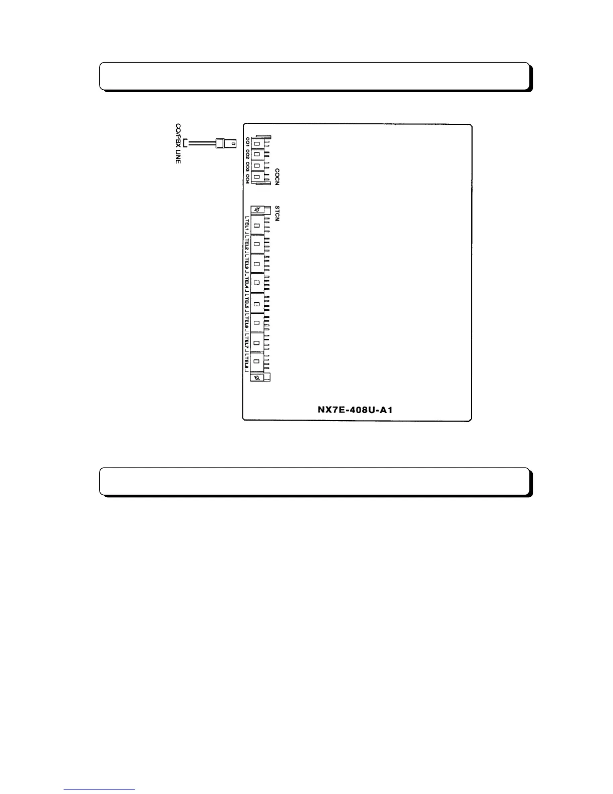
Trunk Line Connection
Extension Connection
The extension (Key Telephone or Single Line Telephone) shall be connected as illustration. Insert the
connector from the extension into the female connector on the units (NX7E-408U-A1, NX7E-008U-A1)
labeled STCN.
The TX-Z 2464 Main Equipment can be installed sixty-four extension ports maximum. A unit (NX7E-
408U-A1 or NX7E-008U-A1) provides eight interface circuits for extension. The maximum number of
NX7E-408U-A1 and NX7E-008U-A1 units that can be installed in a system is as follows:
Basic System (TX-Z 1232): 3 units of 408U-A1 (or 008U-A1) and 1 unit of 008U-A1.
Expanded System (TX-Z 2464): 6 units of 408U-A1 (or 008U-A1) and 2 units of 008U-A1.
(NX7E-24EPMB is required)
4-conductor wiring is required for each extension when connecting Key Telephone Set to the system.
Use 2-conductor wiring for each extension when connecting Single Line Telephone to the system. In
other words, L (Low) and H (High) will not be used for Single Line Telephone.