— 9-44 —
P LM: LED Mode
This parameter monitors the state of connector CN2 (Control input/output connector) via 7
segments LED.
Category Parameter
Format
LM data
0
: Normal mode
1
: Displays state of control output signal.
Data range
2
: Displays state of control input signal.
Shipping set 0
The parameter LM1 displays the state after application of the parameter ST (Stability timer).
The parameter LM2 displays the state after application of the parameter AB (Input port polarity)
and the parameter NW (Anti-chattering stability timer).
POWER LED turns to red in case of an alarm regardless the display mode.
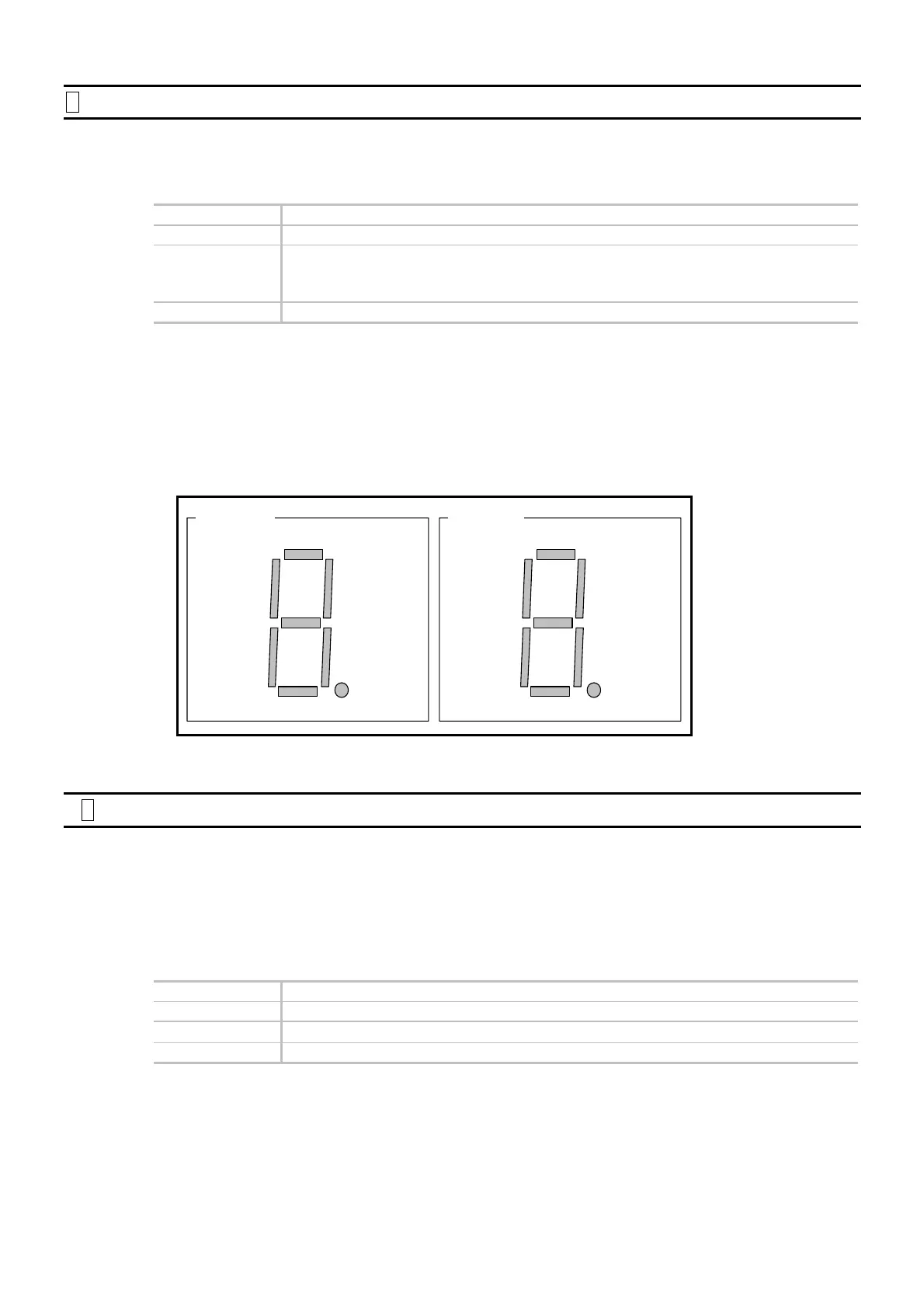
Figure 9-7: Display of LED for state of control Input/Ouput
PO0
PO1
PO2
PO3
PO4
PO5
PO6
PO7
Parameter LM1
PI0
PI1
PI2
PI3
PI4
PI5
PI6
PI7
Parameter LM2
Ì
P LO: Load Inertia
Sets the load moment of inertia of the Motor.
◊ Refer to “5.3.1. Input of Load Inertia” for details
Be sure to specify the load inertia to improve the follow-up capability to a motion command and
the settling time at the end of a positioning.
Category Parameter
Format
LO data
Data range
0.000 to 4 000.000 [kg・m
2
]
Shipping set 0.000
Change of the parameter LO clears the parameter SG (Servo gain) to zero.

 Loading...


