192 KByte Flash Module (S12FTMRG192K2V1)
MC9S12G Family Reference Manual Rev.1.27
1116 NXP Semiconductors
Upon clearing CCIF to launch the Set Field Margin Level command, the Memory Controller will set the
field margin level for the targeted block and then set the CCIF flag.
NOTE
When the EEPROM block is targeted, the EEPROM field margin levels are
applied only to the EEPROM reads. However, when the P-Flash block is
targeted, the P-Flash field margin levels are applied to both P-Flash and
EEPROM reads. It is not possible to apply field margin levels to the P-Flash
block only.
Valid margin level settings for the Set Field Margin Level command are defined in Table 30-58.
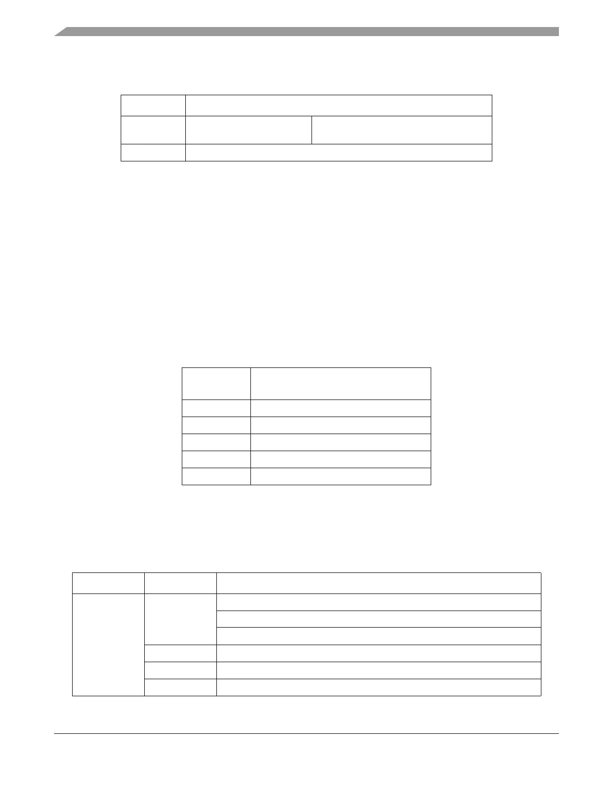
Table 30-57. Set Field Margin Level Command FCCOB Requirements
CCOBIX[2:0] FCCOB Parameters
000 0x0E
Flash block selection code [1:0]
. See
Table 30-34
001 Margin level setting.
Table 30-58. Valid Set Field Margin Level Settings
CCOB
(CCOBIX=001)
Level Description
0x0000 Return to Normal Level
0x0001 User Margin-1 Level
1
1
Read margin to the erased state
0x0002 User Margin-0 Level
2
2
Read margin to the programmed state
0x0003 Field Margin-1 Level
1
0x0004 Field Margin-0 Level
2
Table 30-59. Set Field Margin Level Command Error Handling
Register Error Bit Error Condition
FSTAT
ACCERR
Set if CCOBIX[2:0] != 001 at command launch.
Set if command not available in current mode (see Table 30-27).
Set if an invalid margin level setting is supplied.
FPVIOL None
MGSTAT1 None
MGSTAT0 None

 Loading...


