Port Integration Module (S12GPIMV1)
MC9S12G Family Reference Manual Rev.1.27
206 NXP Semiconductors
NOTE
If the input is driven to active level (IRQ=0) a write access to set either
IRQCR[IRQEN] and IRQCR[IRQE] to 1 simultaneously or to set
IRQCR[IRQEN] to 1 when IRQCR[IRQE]=1 causes an IRQ interrupt to be
generated if the I-bit is cleared. Refer to Section 2.6.3, “Enabling IRQ
edge-sensitive mode”.
2.4.3.14 Reserved Register
1
Read: Anytime
Write:
IRQE: Once in normal mode, anytime in special mode
IRQEN: Anytime
Table 2-34. IRQCR Register Field Descriptions
Field Description
7
IRQE
IRQ select edge sensitive only—
1 IRQ
pin configured to respond only to falling edges. Falling edges on the IRQ pin are detected anytime when
IRQE=1 and will be cleared only upon a reset or the servicing of the IRQ interrupt.
0 IRQ
pin configured for low level recognition
6
IRQEN
IRQ enable—
1 IRQ pin is connected to interrupt logic
0 IRQ
pin is disconnected from interrupt logic
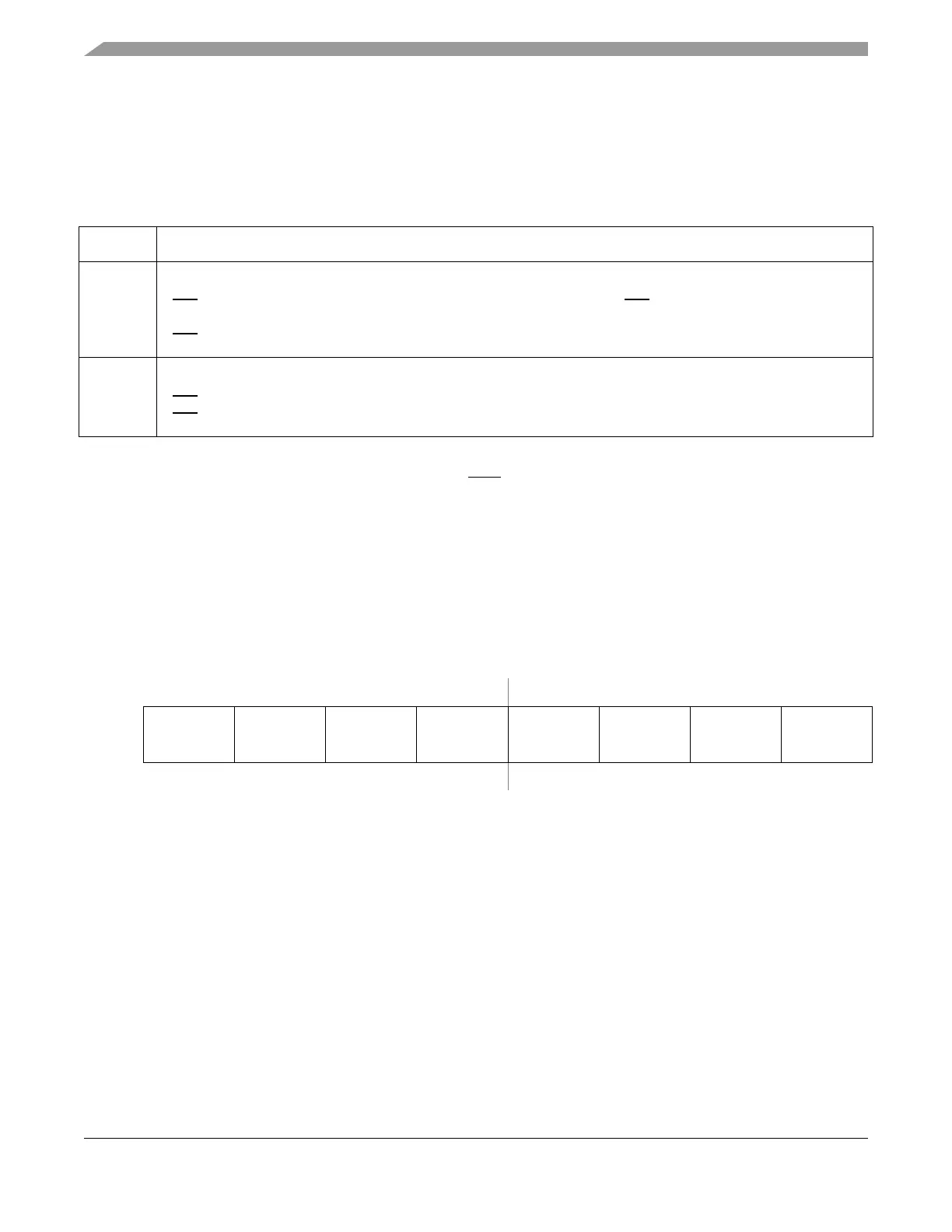
Address 0x001F Access: User read/write
1
1
Read: Anytime
Write: Only in special mode
These reserved registers are designed for factory test purposes only and are
not intended for general user access. Writing to these registers when in
special mode can alter the module’s functionality.
76543210
R
Reserved Reserved Reserved Reserved Reserved Reserved Reserved Reserved
W
Resetxxxxxxxx
Figure 2-15. Reserved Register

 Loading...


