RL78/G15 CHAPTER 5 CLOCK GENERATOR
R01UH0959EJ0110 Rev.1.10 Page 148 of 765
Mar 7, 2023
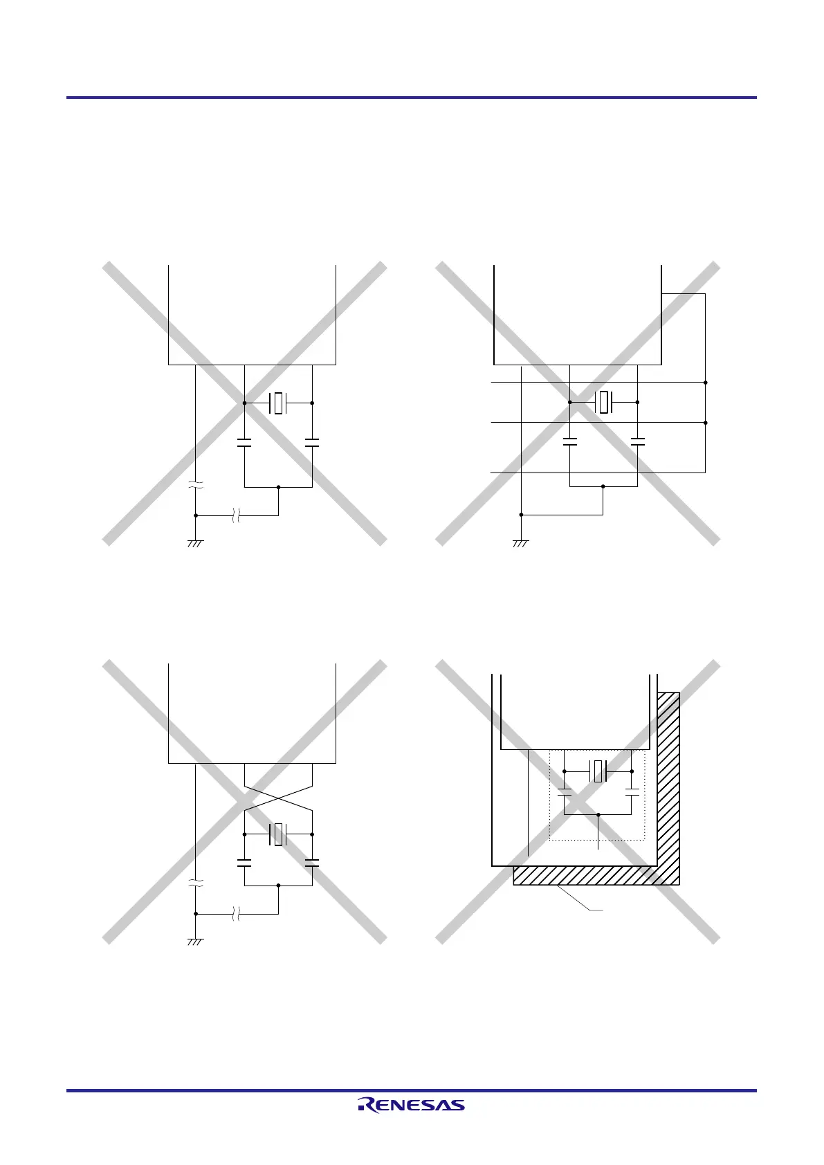
Figure 5-12 shows examples of incorrect resonator connection.
Figure 5-12. Examples of Incorrect Resonator Connection (1/2)
(a) Too long wiring
(b) Crossed signal line
(c) The X1 and X2 signal line wires cross.
(d) A power supply/GND pattern exists under the X1 and
X2 wires.
V
SS
X1 X2
Power supply/GND
pattern
Note 1
Note 1. Do not place a power supply/GND pattern under the wiring section (section indicated by a broken line in the
figure) of the X1 pin and X2 pin and the resonators in a multi-layer board or double-sided board.
Do not configure a layout that will cause capacitance elements and affect the oscillation characteristics.
 Loading...


