RL78/G15 CHAPTER 6 TIMER ARRAY UNIT
R01UH0959EJ0110 Rev.1.10 Page 187 of 765
Mar 7, 2023
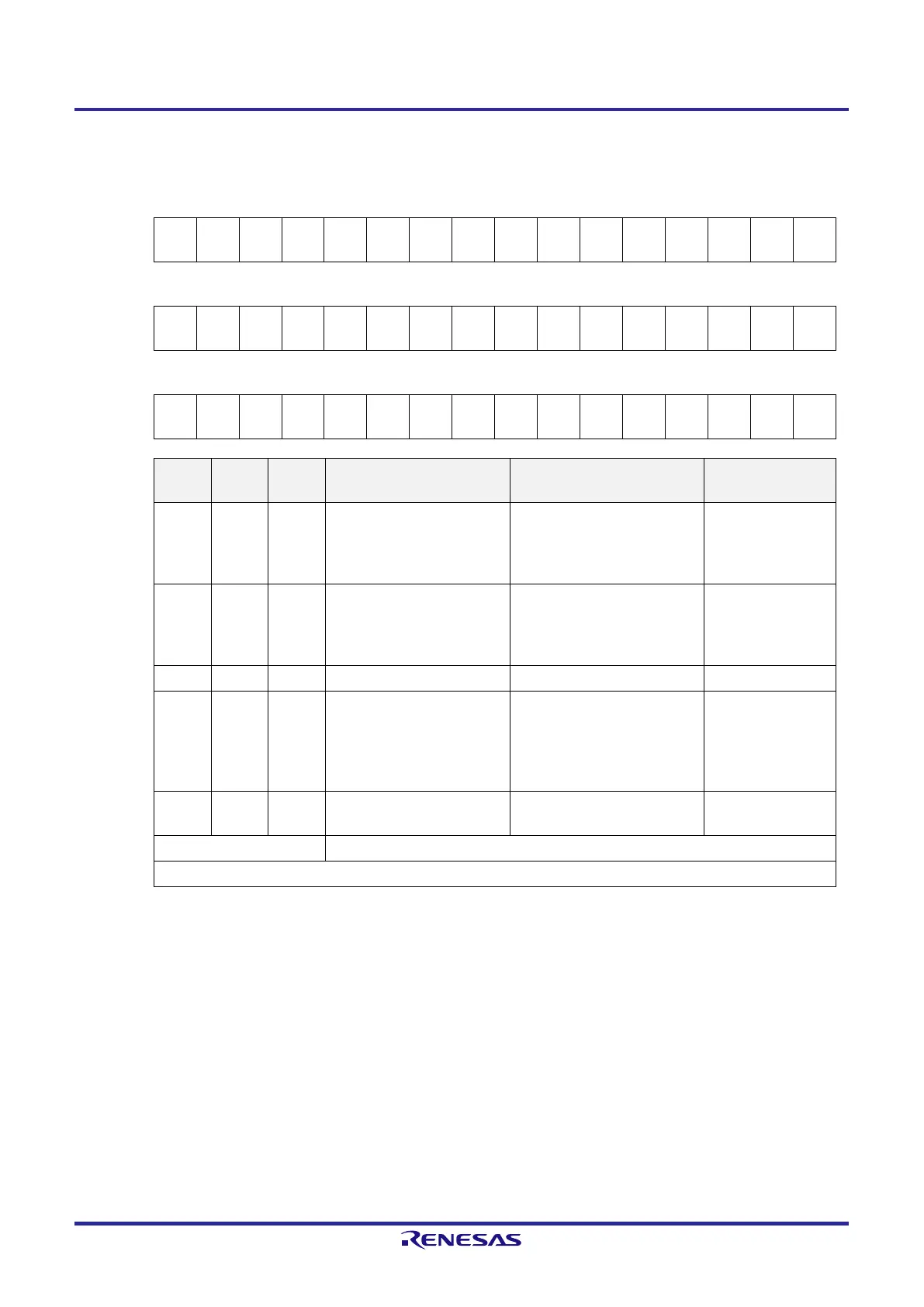
Figure 6-11. Format of Timer Mode Register mn (TMRmn) (4/5)
Address: F0190H, F0191H (TMR00) to F019EH, F019FH (TMR07) After reset: 0000H R/W
Symbol 15 14 13 12 11 10 9 8 7 6 5 4 3 2 1 0
TMRmn
(n = 2, 4, 6
CKSm
n1
CKSm
n0
0
CCSm
n
MAST
ERmn
2
1
0
CISmn
1
CISmn
0
0 0
MDmn
3
MDmn
2
MDmn
1
MDmn
0
Symbol 15 14 13 12 11 10 9 8 7 6 5 4 3 2 1 0
TMRmn
(n = 1, 3)
CKSm
n1
CKSm
n0
0
CCSm
n
SPLIT
mn
2
1
0
CISmn
1
CISmn
0
0 0
MDmn
3
MDmn
2
MDmn
1
MDmn
0
Symbol 15 14 13 12 11 10 9 8 7 6 5 4 3 2 1 0
TMRmn
(n = 0, 5, 7
CKSm
n1
CKSm
n0
0
CCSm
n
0
Note 1
2
1
0
CISmn
1
CISmn
0
0 0
MDmn
3
MDmn
2
MDmn
1
MDmn
0
MDmn3 MDmn2 MDmn1
Setting of operation mode of
channel n
Corresponding function
Corresponding
function
0 0 0 Interval timer mode
Interval timer/
Square wave output/
Divider function/
PWM output (master)
Down count
0 1 0 Capture mode
Input pulse interval
measurement/
Two-channel input with one-shot
pulse output function (slave)
Up count
0 1 1 Event counter mode External event counter Down count
1 0 0 One-count mode
Delay counter/
One-shot pulse output/
Two-channel input with one-shot
pulse output function (master)
PWM output (slave)
Down count
1 1 0 Capture & one-count mode
Measurement of high-/low-level
width of input signal
Up count
Other than above Setting prohibited
The operation of each mode varies depending on MDmn0 bit (see the table below).
Note 1. Bit 11 is a read-only bit and fixed to 0. Writing to this bit is ignored.
Remark m: Unit number (m = 0), n: Channel number (n = 0 to 7)
 Loading...


