RL78/G15 CHAPTER 6 TIMER ARRAY UNIT
R01UH0959EJ0110 Rev.1.10 Page 186 of 765
Mar 7, 2023
Note 1. Bit 11 is a read-only bit and fixed to 0. Writing to this bit is ignored.
Remark m: Unit number (m = 0), n: Channel number (n = 0 to 7)
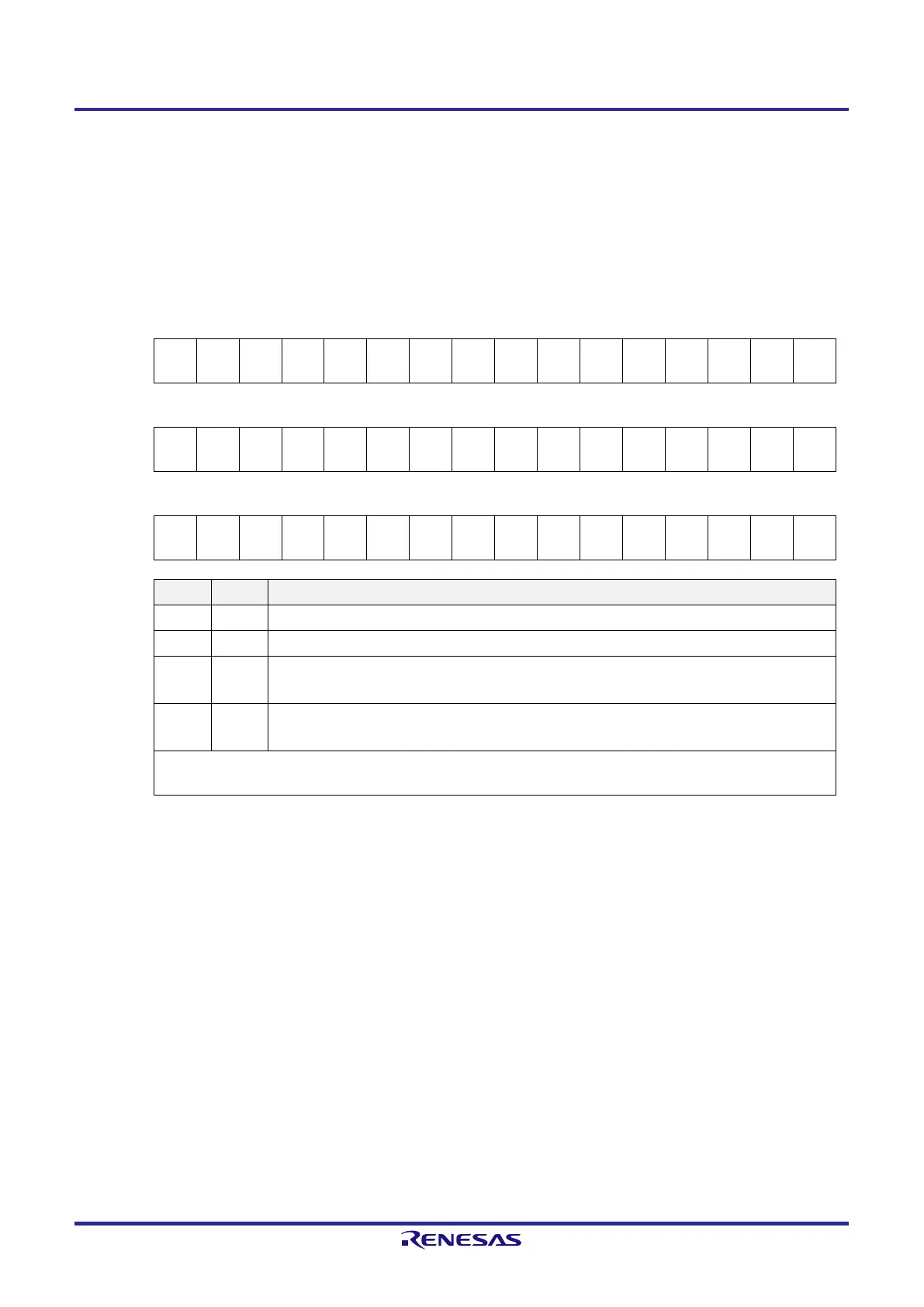
Figure 6-11. Format of Timer Mode Register mn (TMRmn) (3/5)
Address: F0190H, F0191H (TMR00) to F019EH, F019FH (TMR07) After reset: 0000H R/W
Symbol 15 14 13 12 11 10 9 8 7 6 5 4 3 2 1 0
TMRmn
(n = 2, 4, 6
CKSm
n1
CKSm
n0
0
CCSm
n
MAST
ERmn
2
1
0
CISmn
1
CISmn
0
0 0
MDmn
3
MDmn
2
MDmn
1
MDmn
0
Symbol 15 14 13 12 11 10 9 8 7 6 5 4 3 2 1 0
TMRmn
(n = 1, 3)
CKSm
n1
CKSm
n0
0
CCSm
n
SPLIT
mn
2
1
0
CISmn
1
CISmn
0
0 0
MDmn
3
MDmn
2
MDmn
1
MDmn
0
Symbol 15 14 13 12 11 10 9 8 7 6 5 4 3 2 1 0
TMRmn
(n = 0, 5, 7
CKSm
n1
CKSm
n0
0
CCSm
n
0
Note 1
2
1
0
CISmn
1
CISmn
0
0 0
MDmn
3
MDmn
2
MDmn
1
MDmn
0
CISmn1 CISmn0 Selection of TImn pin input valid edge
0 0 Falling edge
0 1 Rising edge
1 0 Both edges (when low-level width is measured)
Start trigger: Falling edge, Capture trigger: Rising edge
1 1 Both edges (when high-level width is measured)
Start trigger: Rising edge, Capture trigger: Falling edge
If both the edges are specified when the value of the STSmn2 to STSmn0 bits is other than 010B, set the CISmn1 to
CISmn0 bits to 10B.
Note 1. Bit 11 is a read-only bit and fixed to 0. Writing to this bit is ignored.
Remark m: Unit number (m = 0), n: Channel number (n = 0 to 7)
 Loading...


