RL78/G15 CHAPTER 6 TIMER ARRAY UNIT
R01UH0959EJ0110 Rev.1.10 Page 243 of 765
Mar 7, 2023
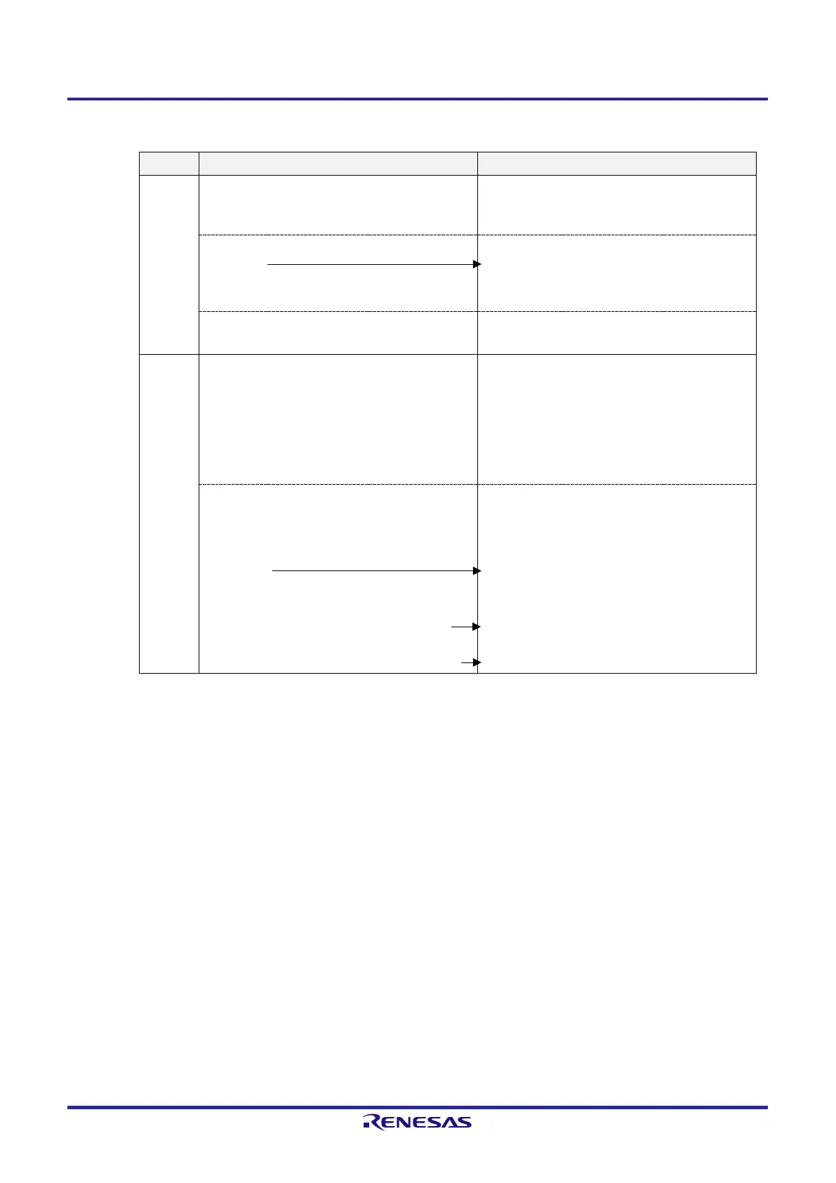
Figure 6-51. Operation Procedure When Frequency Divider Function Is Used (1/2)
Software Operation Hardware Status
TAU
default
setting
Power-off status
(Clock supply is stopped and writing to each register
is disabled.)
Sets the TAU0EN bit of peripheral enable register 0
(PER0) to 1.
Power-on status. Each channel stops operating.
(Clock supply is started and writing to each register is
enabled.)
Sets timer clock select register 0 (TPS0).
Determines clock frequencies of CK00 to CK03.
Channel
default
setting
Sets the corresponding bit of the noise filter enable
register 1 (NFEN1) to 0 (off) or 1 (on).
Sets timer mode register 0n (TMR0n) (determines
operation mode of channel and selects the detection
edge).
Sets interval (period) value to timer data register 0n
(TDR0n).
Channel stops operating.
(Clock is supplied and some power is consumed.)
Clears the TOM0n bit of timer output mode register 0
(TOM0) to 0 (master channel output mode).
Clears the TOL0n bit to 0.
Sets the TO0n bit and determines default level of the
TO0n output.
The TO0n pin goes into Hi-Z output state.
The TO0n default setting level is output when the port
mode register is in output mode and the port register
is 0.
Sets the TOE0n bit to 1 and enables operation of
TO0n.
Clears the port register and port mode register to 0.
TO0n does not change because channel stops
operating.
The TO0n pin outputs the TO0n set level.
Remark n: Channel number (n = 0, 3)
 Loading...


