RL78/G15 CHAPTER 6 TIMER ARRAY UNIT
R01UH0959EJ0110 Rev.1.10 Page 298 of 765
Mar 7, 2023
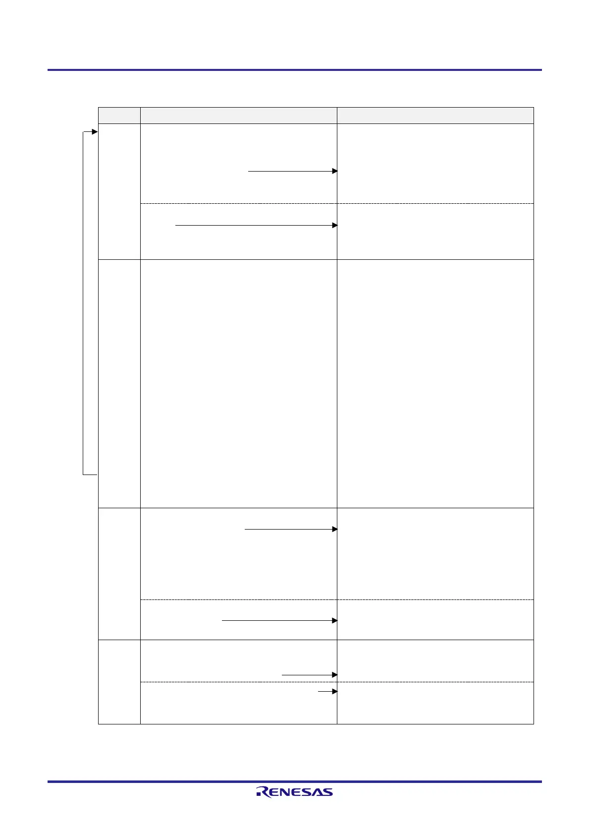
Figure 6-83. Operation Procedure of Two-channel Input with One-shot Pulse Output Function (2/2)
Software Operation Hardware Status
Operation is resumed.
Operation
start
Sets the TOE0p bit of the slave channel to 1 to enable
TO0p operation (only when operation is resumed).
Sets the target bits of the TS0 register (master and
slave) to 1 at the same time.
The target bits of the TS0 register automatically
return to 0 because they are trigger bits.
The target bits of the TE0 register are set to 1 and the
master channel enters the TI0n pin input valid edge
detection wait status.
Count operation starts on detection of the next start
triggers:
●
The TI0n pin input valid edge is detected.
●
The TS0n bit is set to 1 by software.
Value of the TDR0n register is loaded to the timer
count register 0n (TCR0n) of the master channel, and
count down operation starts.
During
operation
Changes master channel setting.
The TCR0n register can always be read (for the
access procedure to the TCR0nH and TCR0nL
registers, see 6.2.1 Timer count register mn
(TCRmn)).
The set values of only the CIS0n1 and CIS0n0 bits
of the TMR0n register can be changed.
The set values in the target bits of the TDR0n,
TO0, TOE0, TOM0, and TOL0 registers cannot be
changed.
Changes slave channel setting.
The TDR0p register can always be read.
The TCR0p register can always be read.
The TSR0p register can always be read.
The set values of only the CIS0p1 and CIS0p0 bits
of the TMR0p register can be changed.
The set values in the target bits of the TO0p,
TOE0p, TOM0, and TOL0 registers cannot be
changed.
The master channel counter (TCR0n) performs count
down operation. When the count value reaches
TCR0n = 0000H, INTTM0n is generated, and the
counter stops at TCR0n = FFFFH until the next start
trigger is detected (the TI0n pin input valid edge is
detected or TS0n bit is set to 1).
The slave channel, triggered by INTTM0n of the
master channel, clears the timer counter register 0p
(TCR0p) to 0000H. The counter (TCR0p) starts
counting up from 0000H, and when the TI0n pin input
valid edge is detected, the count value is transferred
to the timer data register 0p (TDR0p) (capture) and
the TCR0p register is cleared to 0000H. At this time,
INTTM0p is generated, which sets the TO0p output
level to inactive.
After that, the above operation is repeated.
Operation
stop
Sets the target bits of the TT0 register (master and
slave) to 1 at the same time.
The target bits of the TT0 register automatically
return to 0 because they are trigger bits.
The target bits of the TE0 register are cleared to 0,
and count operation stops.
The TCR0n and TCR0p registers hold count value
and stop.
The TO0p output is not initialized but holds current
status.
Clears the TOE0p bit of slave channel to 0 and sets a
value to the TO0p bit.
The level set in the TO0p bit is output from the TO0p
pin.
TAU stop To hold the TO0p pin output level
Clears the TO0p bit to 0 after the value to be held
(output latch) is set to the port register.
The TO0p pin output level is held by port function.
Clears the TAU0EN bit of the PER0 register to 0. Power-off status
(Clock supply is stopped and SFR of the TAU is
initialized.)
Remark n: Master channel number (n = 0, 2)
p: Slave channel number (p = 3)
 Loading...


