RL78/G15 CHAPTER 12 SERIAL ARRAY UNIT
R01UH0959EJ0110 Rev.1.10 Page 375 of 765
Mar 7, 2023
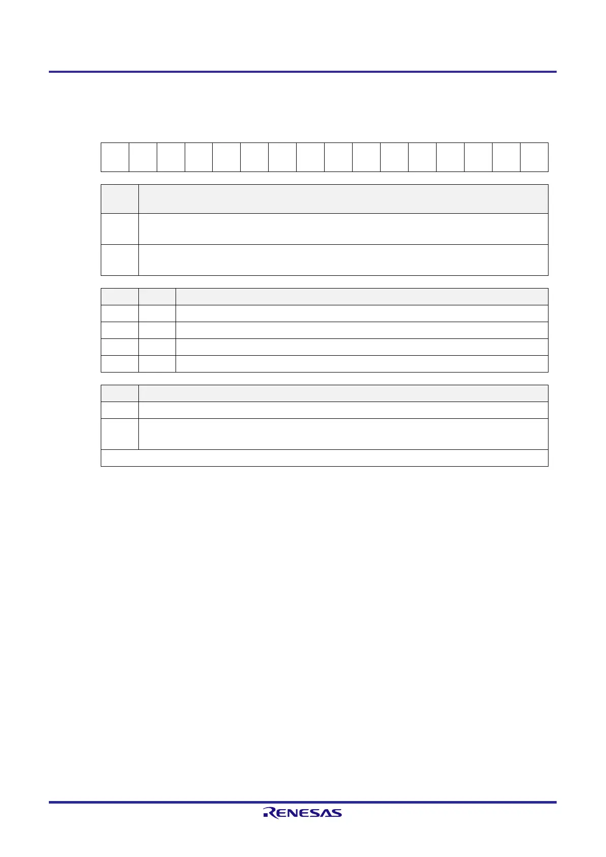
Figure 12-5. Format of Serial Mode Register mn (SMRmn) (2/2)
Address: F0110H, F0111H (SMR00) to F0112H, F0113H (SMR01) After reset: 0020H R/W
Symbol 15 14 13 12 11 10 9 8 7 6 5 4 3 2 1 0
SMRmn
CKSm
n
CCSm
n
0 0 0 0 0
Note 1
0
SISmn
0
Note 1
1 0 0
MDmn
2
MDmn
1
MDmn
0
SISmn0
Note 1
Controls inversion of level of receive data of channel n in UART mode
0 Falling edge is detected as the start bit.
The input communication data is captured as is.
1 Rising edge is detected as the start bit.
The input communication data is inverted and captured.
MDmn2 MDmn1 Setting of operation mode of channel n
0 0 Simplified SPI (CSI) mode
0 1 UART mode
1 0 Simplified I
2
C mode
1 1 Setting prohibited
MDmn0 Selection of interrupt source of channel n
0 Transfer end interrupt
1 Buffer empty interrupt
(Occurs when data is transferred from the SDRmn register to the shift register.)
For continuous transmission, set this bit to 1 and write the next transmit data when SDRmn data has run out.
Note 1. The SMR01 register only.
Caution Be sure to clear bits 13 to 9, 7, 4, and 3 (or bits 13 to 6, 4, and 3 for the SMR00 register) to 0. Be sure
to set bit 5 to 1.
Remark m: Unit number (m = 0), n: Channel number (n = 0, 1), p: CSI number (p = 00, 01)
q: UART number (q = 0), r: IIC number (r = 00, 01)
 Loading...


