RL78/G15 CHAPTER 13 SERIAL INTERFACE IICA
R01UH0959EJ0110 Rev.1.10 Page 515 of 765
Mar 7, 2023
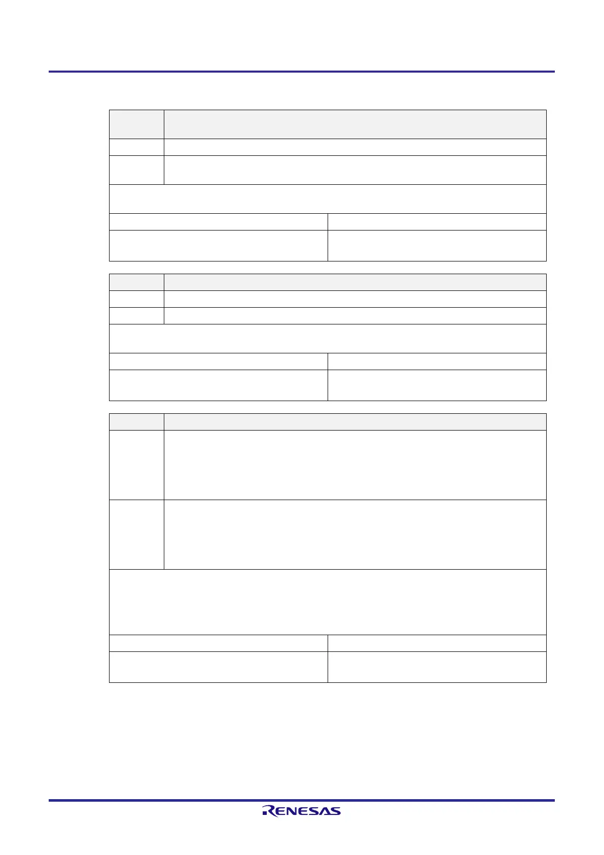
Figure 13-6. Format of IICA Control Register 00 (IICCTL00) (2/4)
WREL0
Note 2, Note 3
Release clock stretching
0 Clock stretching is not released.
1
Clock stretching is released. This bit is automatically cleared to 0 after clock stretching has been
released.
When the WREL0 bit is set (clock stretching is released) during the clock stretch period at the 9th clock pulse in the
transmission state (TRC0 = 1), the SDAA0 line goes into the high impedance state (TRC0 = 0).
Condition for clearing (WREL0 = 0) Condition for setting (WREL0 = 1)
●
Automatically cleared after execution
●
Reset
●
Set by instruction
SPIE0
Note 4
Enable/disable generation of interrupt request when stop condition is detected
0 Disable
1 Enable
If the WUP0 bit of IICA control register 01 (IICCTL01) is 1, no stop condition interrupt will be generated even if SPIE0 =
1.
Condition for clearing (SPIE0 = 0) Condition for setting (SPIE0 = 1)
●
Cleared by instruction
●
Reset
●
Set by instruction
WTIM0
Note 4
Control of clock stretching and interrupt request generation
0 An interrupt request is generated on the falling edge of the 8th clock.
Master mode: After the output of 8 clock pulses, the clock is stretched while the clock output is at the
low level.
Slave mode: After the input of 8 clock pulses, the clock is set to the low level to stretch the master’s
clock.
1 An interrupt request is generated on the falling edge of the 9th clock.
Master mode: After the output of 9 clock pulses, the clock is stretched while the clock output is at the
low level.
Slave mode: After the input of 9 clock pulses, the clock is set to the low level to stretch the master’s
clock.
An interrupt is generated on the falling edge of the 9th clock during address transfer independently of the setting of this
bit. The setting of this bit is valid after the completion of address transfer. In master mode, clock stretching is applied at
the falling edge of the 9th clock during address transfer. For a slave that has received its local address, clock stretching
is applied at the falling edge of the 9th clock after an acknowledge (ACK) has been issued. However, if the slave has
received an extension code, clock stretching is applied at the falling edge of the 8th clock.
Condition for clearing (WTIM0 = 0) Condition for setting (WTIM0 = 1)
●
Cleared by instruction
●
Reset
●
Set by instruction
 Loading...


