RL78/G15 CHAPTER 13 SERIAL INTERFACE IICA
R01UH0959EJ0110 Rev.1.10 Page 586 of 765
Mar 7, 2023
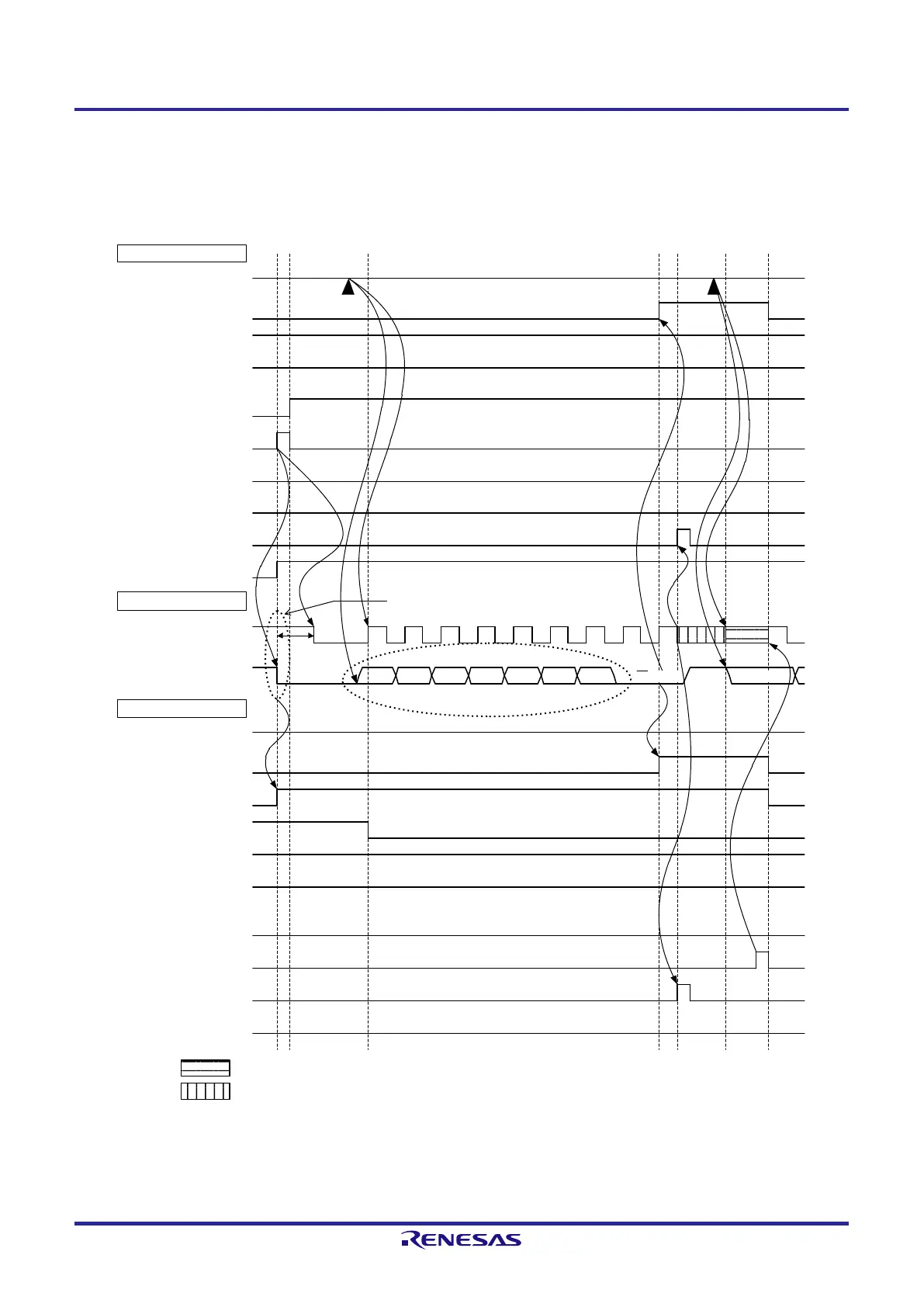
Figure 13-31. Example of Master to Slave Communications
(9th Cycle Clock Stretching is Selected for Both Master and Slave) (1/4)
(1) Start condition ~ address ~ data
IICA
0
ACKD0
(ACK detection)
<1
>
<2>
<
5
>
L
L
H
H
AD5 AD4
Note
1
Start condition
Master side
STT0
(ST trigger
)
SPT
0
(SP trigger
)
WREL0
(
release clock stretching
)
INTIICA0
(interrupt
)
TRC0
(transmission
/
reception)
Bus line
SCLA0 (bus)
(
clock line)
SDAA0 (bus)
(data line
)
AD6 AD3 AD
2 AD1
AD0 D
1
7
Slave side
IICA0
ACKD
0
(ACK detection
)
<3>
<4
>
H
H
L
L
<
6>
Note 3
Slave address
STD0
(ST detection)
SPD0
(SP detection)
WTIM0
(Clock stretch timing control
)
ACKE0
(ACK control
)
MSTS0
(communication state)
WREL0
(release clock stretching
)
INTIICA0
(interrupt)
TRC0
(transmission/reception
)
WTIM0
(Clock stretch timing control
)
ACKE0
(ACK control
)
MSTS0
(communication state)
W ACK
Note
2
:
Clock stretching by the slave
: Clock stretching by the master and slave
Note 1. To release clock stretching in transmission by the master, write data to the IICA0 register instead of setting
the WREL0 bit.
 Loading...


